
Multiple description coding communication system

Inactive Publication Date: 2008-01-31
AMERICAN TELEPHONE & TELEGRAPH CO
View PDF16 Cites 16 Cited by
  • Summary
  • Abstract
  • Description
  • Claims
  • Application Information

AI Technical Summary

Benefits of technology

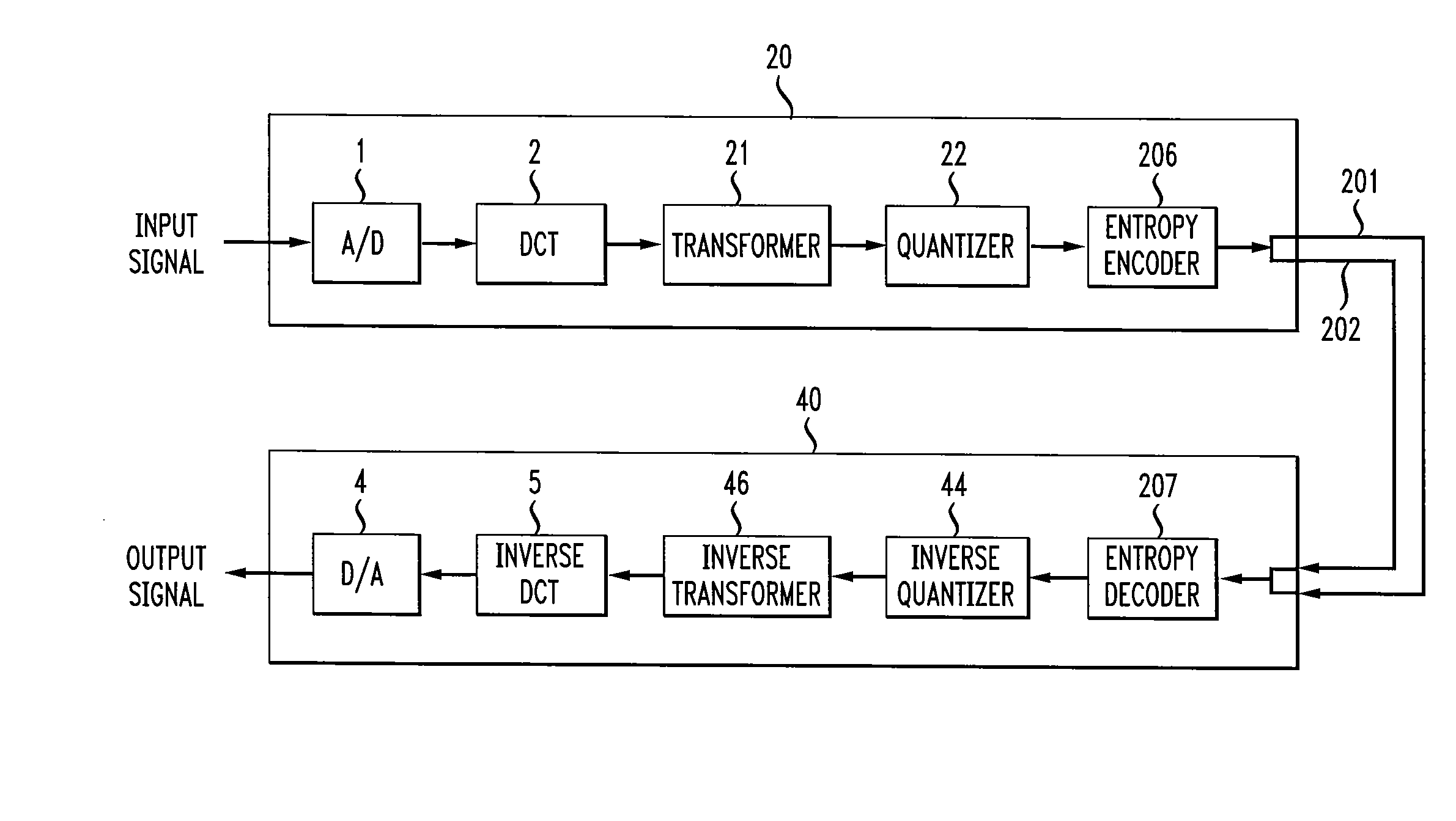
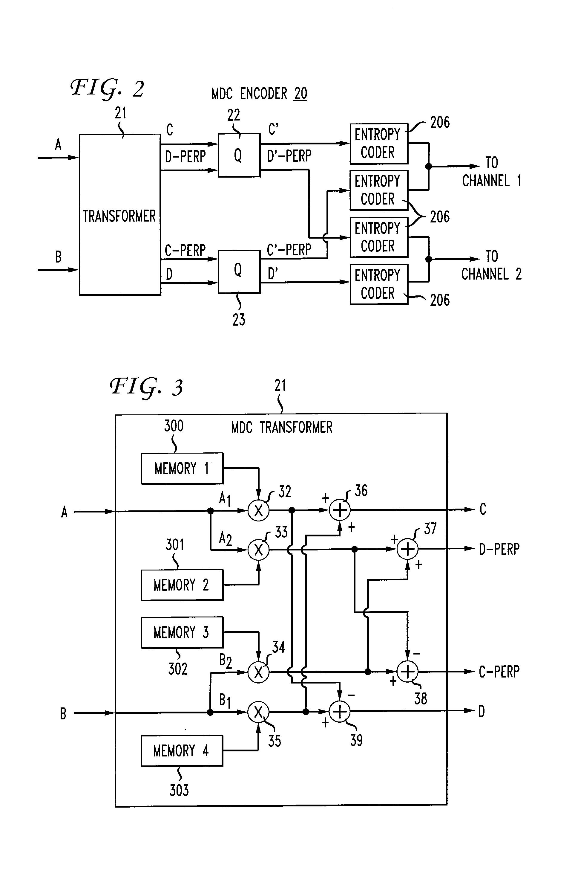
[0015] The present invention describes a method and apparatus for reliably encoding and decoding information over a communication system. The method includes transforming two samples into two pairs of random variables, one random variable in each pair having substantially equal energy as one random variable in the other pair. The method further includes quantizing each of the pairs of random variables separately and entropy coding each qua

Problems solved by technology

This reduces coding efficiency compared to conventional signal description coding (SDC) where there is no redundancy.
With real image and video signals, the redundancy in the signal (such as the correlation among adjacent samples) can help reduce the loss in coding efficiency, but a certain amount of sacrifice in coding efficiency is unavoidable.
However, this reduced coding efficiency is in exchange for increased robustness to long burst errors and / or channel failures.
This is in part because the analytical results hold true at highly efficient coders while their proposed coder is not efficient.
Therefore, the loss in coding efficiency is quite significant, for the value of R being relatively high.
Although more sophisticated quantizer mappings can be designed to improve the coding efficiency, a direct application of this approach to the original samples of a signal is not advisable in terms of loss in coding efficiency.
While offering a good redundancy rate distortion performance at low redundancies, a serious drawback of the two sample transform-based MDC methods is that they fail to reduce one-channel distortion to levels close to two-channel distortion with high redundancies (i.e., near half the total bit rate).

Method used


Image

  • Multiple description coding communication system
  • Multiple description coding communication system
  • Multiple description coding communication system

Examples


Embodiment Construction

[0030] The present invention modifies a conventional transform coder to a multiple description coding (MDC) encoder. Given a block of L samples created from a input signal as in a conventional transform coder, these samples are first transformed into a block of L coefficients using a Discrete Cosine Transform (DCT), for example. It is possible, however to use other types of transforms. Instead of directly quantizing and coding this block of coefficients, the present invention transforms the block of L coefficients into L / 2 pairs of random variables. Each pair of random variables is then quantized. After quantization, each random variable is separately encoded and again paired for bitstream formation and transmission. Ideally, the conversion is such that if both bitstreams are received, then the original transform coefficients can be recovered perfectly in the absence of the quantization error. If only one bitstream is received, the original transform coefficients can still be recove...


PUM


Abstract

A method and apparatus reliably encode and decode information over a communication system. The method includes transforming two coefficients into two pairs of random variables, one random variable in each pair having substantially equal energy as one random variable in the other pair. The method further includes quantizing each of the pairs of random variables and entropy coding each quantized random variable separately creating an encoded bitstreams. The encoded bitstreams are received by a decoder which first determines which channels of the communication system are working. The encoded bitstream is entropy decoded, inversed quantized and inversed transformed. An inverse transform performs three different transformations depending upon which channels are working, i.e., whether the first, second or both channels are working.

Description

CROSS-REFERENCE TO RELATED PATENT APPLICATIONS [0001] This application is a continuation of U.S. patent application Ser. No. 10 / 994,511, filed Nov. 22, 2004 entitled Multiple Description Coding Communication System, currently allowed, which is a divisional of U.S. patent application Ser. No. 09 / 511,367, filed Feb. 23, 2000 entitled Multiple Description Coding Communication System, now U.S. Pat. No. 6,823,018, all of which are herein incorporated by reference in their entirety. [0002] This patent application claims the benefit of U.S. Provisional Application Ser. No. 60 / 145,937 entitled Multiple Description Coding Communication System, filed Jul. 28, 1999. [0003] This patent application is related to the following commonly assigned U.S. Provisional Patent Application: Method and Apparatus for Accomplishing Multiple Description Coding for Video, U.S. Provisional Application Ser. No. 60 / 145,852, filed Jul. 27, 1999. This patent application is also related to the following commonly assi...

Claims


Application Information

Patent Timeline
IPC IPC(8): H04B14/06
CPCH03M7/40H04N19/39H04N19/61
Inventor JAFARKHANI, HAMIDORCHARD, MICHAEL T.REIBMAN, AMY R.WANG, YAO
Owner AMERICAN TELEPHONE & TELEGRAPH CO
Learn More