Method, medium, and system compensating shadow areas

Active Publication Date: 2008-01-31
SAMSUNG ELECTRONICS CO LTD
View PDF17 Cites 21 Cited by
  • Summary
  • Abstract
  • Description
  • Claims
  • Application Information

AI Technical Summary

Benefits of technology

[0011] An aspect of one or more embodiments of the present invention is to provide a technique for realizing a clear image by improving the lum

Problems solved by technology

However, when components of the corresponding luminance signal are uneven or distorted, it is difficult to clearly visually represent an object included in the image.
In particular, when the luminance distribution is uneven, it may be difficult for a viewer to distinguish between objects in dark areas of such an image.
In addition, systems that compensate the luminance consider only the characteristics of a display device, regardless of the input image, and cannot properly compensate the luminance of a low-luminance

Method used


Image

  • Method, medium, and system compensating shadow areas
  • Method, medium, and system compensating shadow areas
  • Method, medium, and system compensating shadow areas

Examples


Example

[0031] Reference will now be made in detail to embodiments of the present invention, examples of which are illustrated in the accompanying drawings, wherein like reference numerals refer to the like elements throughout. Embodiments are described below to explain the present invention by referring to the figures.

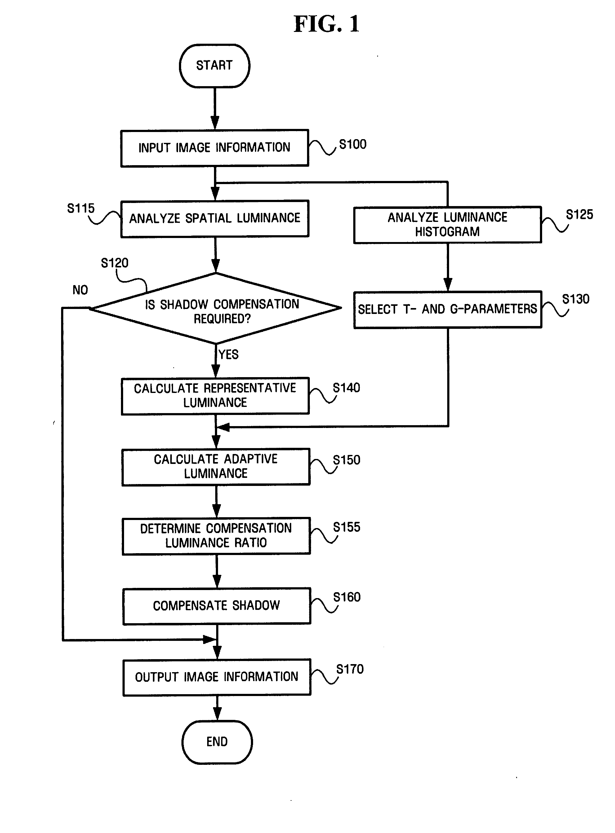
[0032]FIG. 1 illustrates a shadow area compensating method, according to an embodiment of the invention.

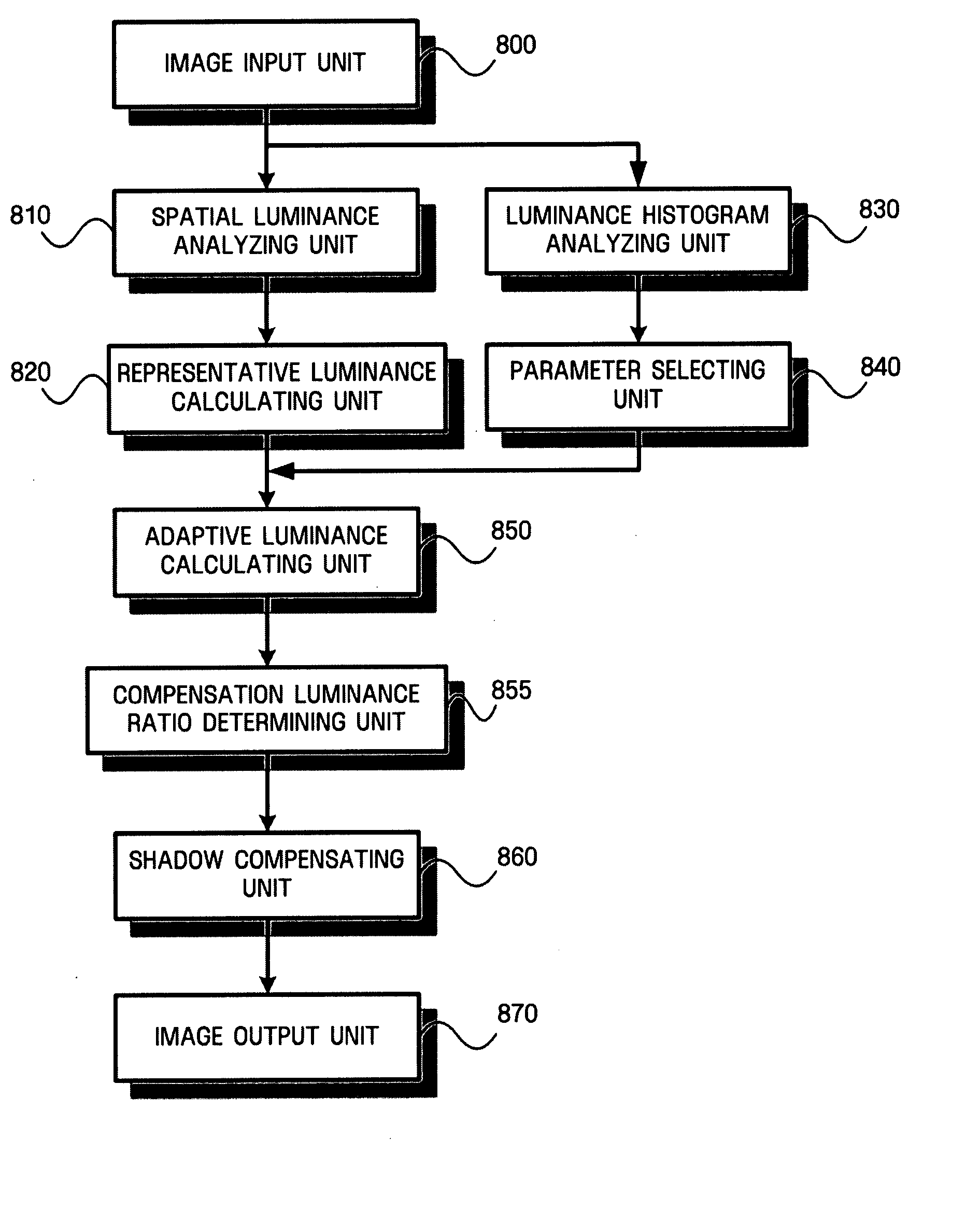
[0033] The shadow area compensating method may include receiving image information, in operation S100, performing spatial luminance analysis, in operation S115, calculating a representative luminance, in operation S140, determining a compensation luminance ratio, in operation S155, compensating a shadow area, in operation S160, and outputting image information, in operation S170.

[0034] As shown in FIG. 1, image information may be input in operation S100, and may include data on the color of every pixel, for example.

[0035] When the input image information is analyzed, th...


PUM


Abstract

An image compensating system, medium, and method, including, a shadow area compensating system, medium, and method which may significantly increase the luminance of each pixel in a dark area with respect to pixels positioned in the vicinity of the corresponding pixel and slightly increase the luminance of each pixel in a bright area. The shadow area compensating method includes calculating a representative luminance Lav of each pixel having image information by reflecting the luminance of the corresponding pixel and the luminances of pixels positioned in the vicinity of the corresponding pixel, determining a compensation luminance ratio using the calculated representative luminance, and increasing an output luminance on the basis of the compensation luminance ratio.

Description

CROSS-REFERENCE TO RELATED APPLICATIONS [0001] This application claims priority from Korean Patent Application No. 10-2006-0072324 filed on Jul. 31, 2006 in the Korean Intellectual Property Office, the disclosure of which is incorporated herein by reference in its entirety. BACKGROUND OF THE INVENTION [0002] 1. Field of the Invention [0003] One or more embodiments of the present invention relate to a shadow area compensating system, medium, and method, and more particularly, to shadow area compensating system, medium, and method which that may significantly increase the luminance of each pixel in a dark area with respect to pixels positioned in the vicinity of the corresponding pixel and slightly increase the luminance of each pixel in a bright area. [0004] 2. Description of the Related Art [0005] Generally, an image input by an image input device includes a variety of information, including luminance and chrominance information, for example. However, when components of the correspo...

Claims


Application Information

Patent Timeline
IPC IPC(8): G06K9/40
CPCG06T5/40G06T5/008G06T7/38H04N1/4072H04N5/57H04N9/64
Inventor HAN, YOUNG-RANLEE, SEUNG-SINPARK, DU-SIK
Owner SAMSUNG ELECTRONICS CO LTD
Why Eureka
Try Eureka