Hand-held power tool with pneumatic percussion mechanism

a technology of percussion mechanism and hand-held power tool, which is applied in the direction of portable percussive tools, boring/drilling equipment, drilling machines and methods, etc., can solve the problems of increased vibrations which must be damped, and the percussion mechanism is not in an optimal operation condition, so as to achieve the effect of dissipating the motion energy in the damping member

Inactive Publication Date: 2008-02-07
HILTI AG
View PDF21 Cites 13 Cited by
  • Summary
  • Abstract
  • Description
  • Claims
  • Application Information

AI Technical Summary

Benefits of technology

[0009]The circumferential radial groove, which is axially limited at its opposite ends, elastically axially limits the displacement of the anvil at the end operational p

Problems solved by technology

At extreme operational conditions, as with working tool-side directed, idle blows, with the working tool being lifted off a constructional component, or at reflected backward, oppositely d

Method used


Image

  • Hand-held power tool with pneumatic percussion mechanism
  • Hand-held power tool with pneumatic percussion mechanism

Examples


Embodiment Construction

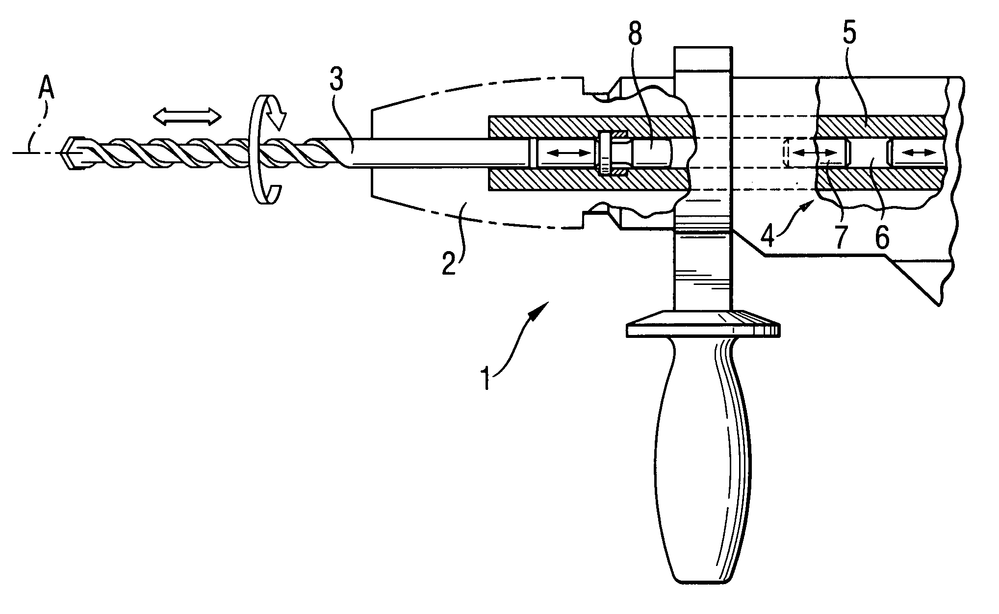
[0018]A hand-held power tool 1 according to the present invention and which is partially shown in FIG. 1, drives, rotationally and percussively, a working tool 3 along an axis A. The working tool 3 is received in a chuck 2 of the power tool 1. The working tool 3 is driven by a percussion mechanism 4 that includes a percussion piston 7 displaceable in a guide tube 5 and reciprocatingly driven by an air spring 6. At its working tool side, the percussion piston 7 impacts an anvil 8 which is axially displaceable, within certain limits and which applies axial blows to the working tool 3.

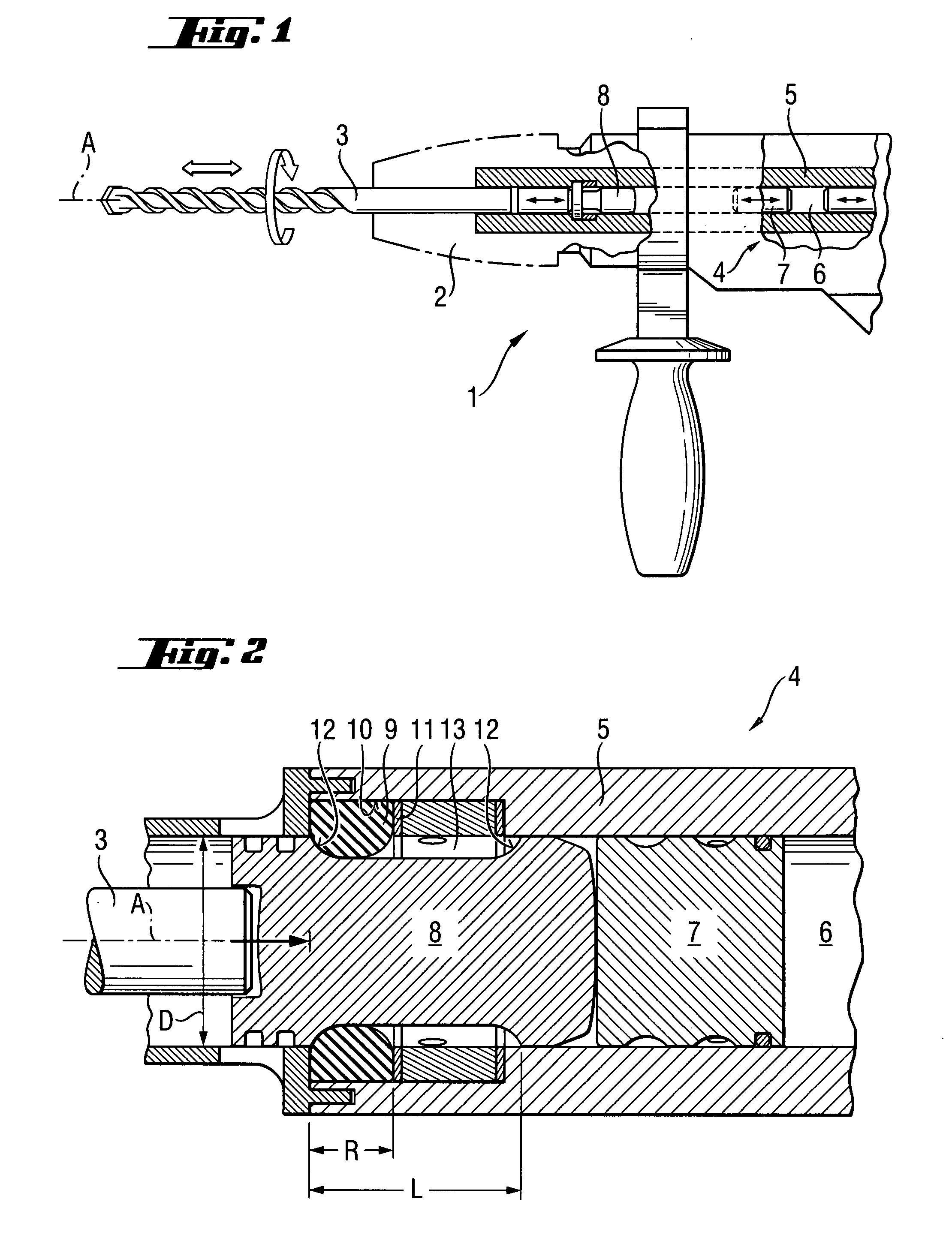
[0019]As shown in FIG. 2, a viscoelastic damping member 9, which is formed of vinylidene-fluoride-hexafluoropropylene (VF2 / HFP) in form of an O-ring, is arranged with its radially outer portion in a radially inner groove 10 which is formed in the guide tube 5. The damping member 9 is axially supported in the groove 10 with an annular disc 11. The damping member 9 engages, with its annular thickness R that...


PUM

PropertyMeasurementUnit
Shapeaaaaaaaaaa

Abstract

A hand-held power tool for percussively driving a working tool (3) includes a percussion mechanism (4) having a guide tube (5), in which a percussion piston (7) which is driven by an air spring (6), is axially displaceable for applying axial impacts to an anvil (8) that applies axial blows to the working tool (3), and a viscoelastic damping member (9) arranged in the guide tube (5) and engaging in a circumferential radial groove (13) of the anvil (8) and which is axially limited at opposite sides thereof.

Description

BACKGROUND OF THE INVENTION[0001]1. Field of the Invention[0002]The present invention relates to a percussion hand-held power tool with a pneumatic percussion mechanism such as, e.g., chisel hammer or hammer drill.[0003]2. Description of the Prior Art[0004]A percussion mechanism of a percussion hand-held power tool includes a percussion piston, which is displaceable in a guide tube and is driven by an air spring and which applies axial blows to an axially displaceable, within certain limits, anvil that itself imparts blows to an end surface of an axially displaceable, also within certain limits, working tool.[0005]At extreme operational conditions, as with working tool-side directed, idle blows, with the working tool being lifted off a constructional component, or at reflected backward, oppositely directed, hammer blows upon encountering reinforcement, the percussion mechanism is not any more in an optimal operational condition and generates increased vibrations which must be damped...

Claims


Application Information

Patent Timeline
IPC IPC(8): B25D9/04
CPCB25D11/005B25D16/00B25D2217/0015B25D2222/66B25D2250/131B25D17/06
Inventor HAMMERSTINGL, STEFAN
Owner HILTI AG
Why Eureka
Try Eureka