
Muffler for an exhaust system of an internal combustion engine

a technology of exhaust system and muffler, which is applied in the direction of gas chamber, gas passage, silencing apparatus, etc., can solve the problems of difficult prediction, unfavorable noise generation of the branch pipe, and annoying noises

Active Publication Date: 2019-12-05
FAURECIA EMISSIONS CONTROL TECH GERMANY
View PDF0 Cites 0 Cited by
  • Summary
  • Abstract
  • Description
  • Claims
  • Application Information

AI Technical Summary

Benefits of technology

The invention is a muffler that reduces whistling noises in a branch pipe without affecting its desired acoustic function. It achieves this by damping pipe length resonances, particularly downstream perforations, and avoids the need for costly and difficult-to-manufacture destroying measures. The muffler has a constant or substantially constant pipe cross-section, making it easier to predict and manufacture. It also has a curved section that can be adjusted to different installation space conditions. Overall, the muffler provides an effective solution for reducing whistling noises in branch pipes.

Problems solved by technology

However, depending on flow velocity and temperature, such branch pipes tend to produce undesired whistling noises.
Such noises can be very annoying and are difficult to predict in the development phase, as they partly occur only under certain driving conditions, for example after a cold start and at an engine load of 80%.
However, this is not always possible or associated with very high costs.
It is therefore difficult to ensure a constant good quality of the exhaust systems in terms of noise generation.

Method used


Image

  • Muffler for an exhaust system of an internal combustion engine
  • Muffler for an exhaust system of an internal combustion engine
  • Muffler for an exhaust system of an internal combustion engine

Examples


Embodiment Construction

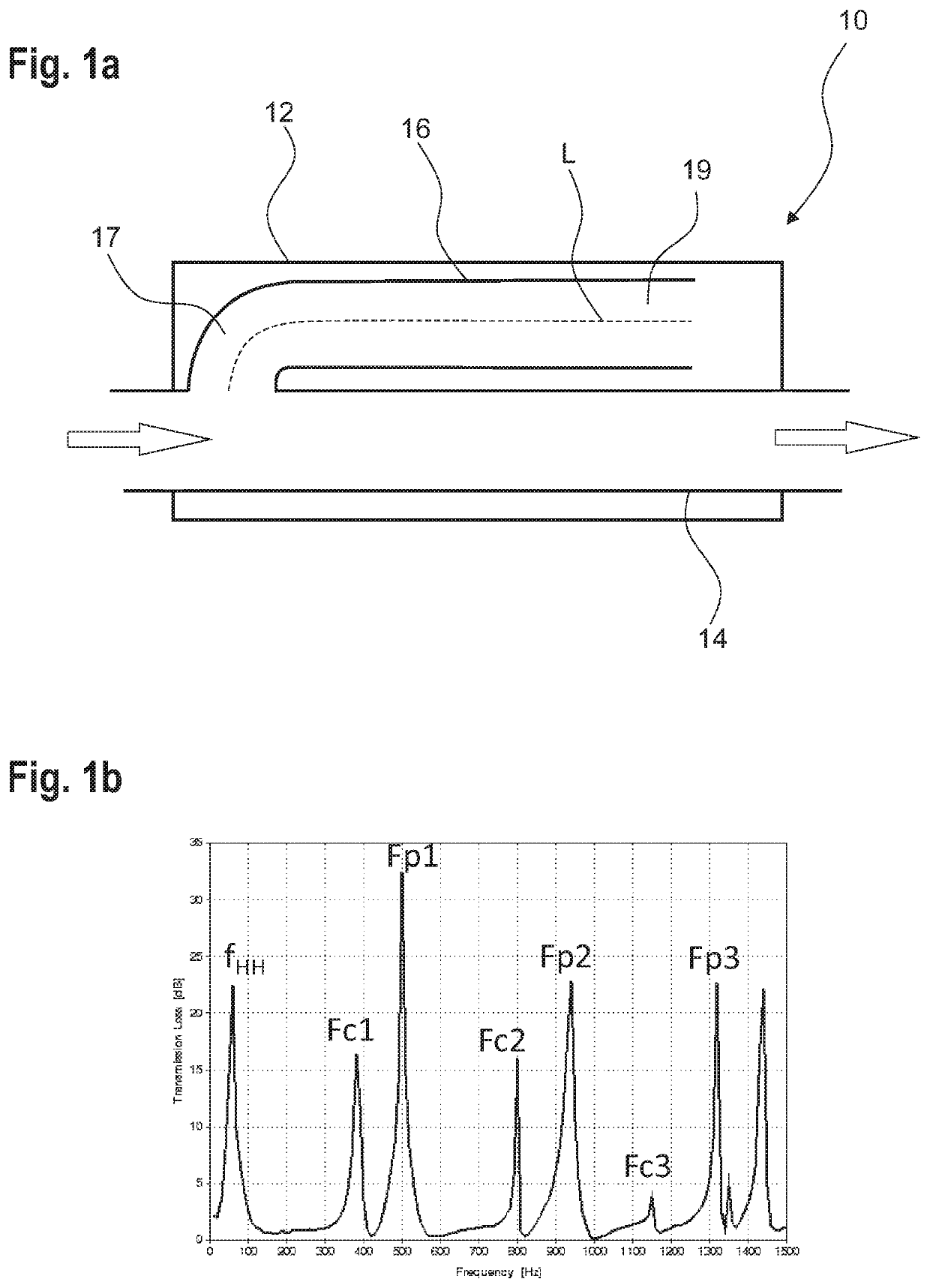
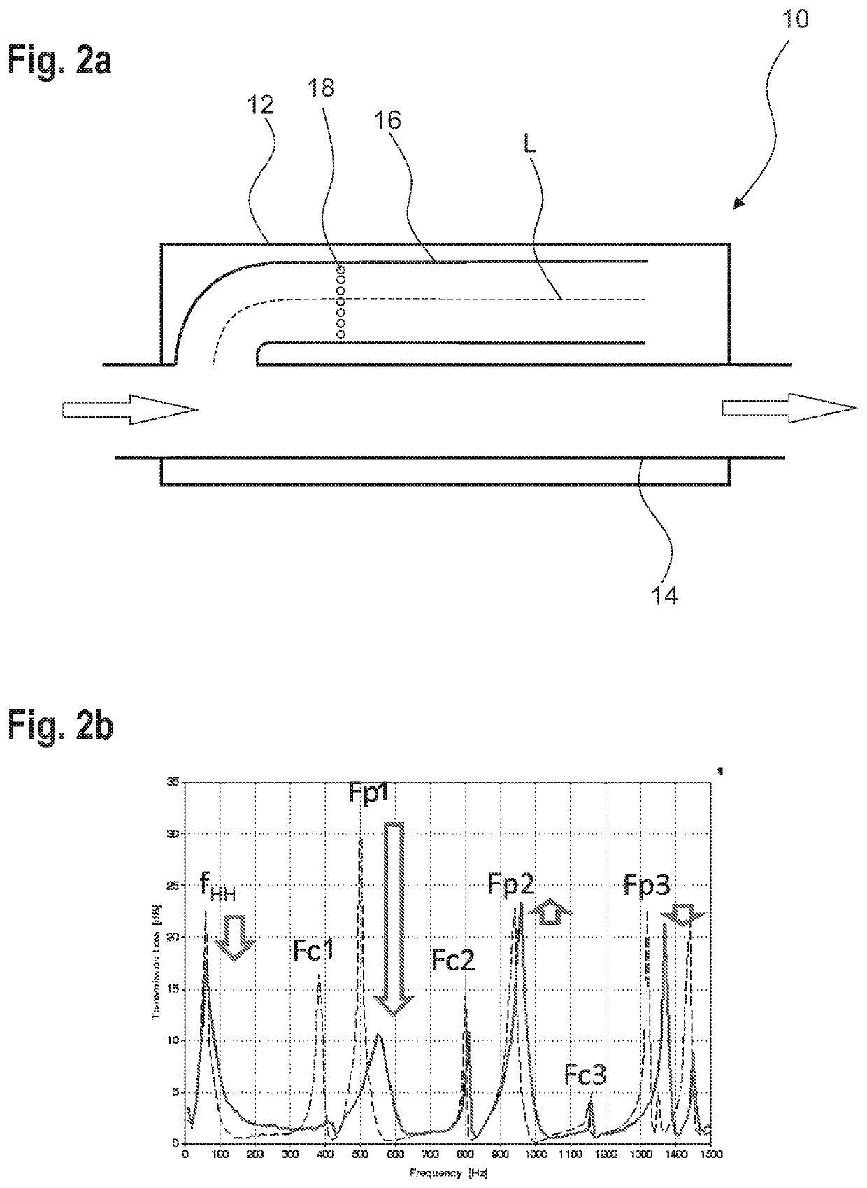
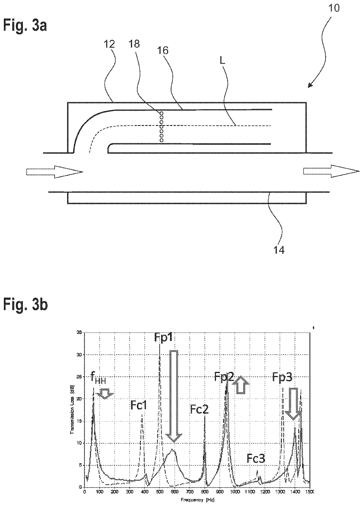
[0044]FIG. 1a schematically shows a longitudinal section of an exemplary muffler 10. The basic structure and the operating principle of a muffler 10 is to be explained on the basis of FIG. 1a.

[0045]The muffler 10 is suitable for an exhaust system of an internal combustion engine, in particular for a motor vehicle. The muffler 10 includes a housing 12 having a through pipe 14 which conducts exhaust gas during operation of the muffler 10 and which is guided through the housing 12, the exhaust gas flowing through the through pipe 14 in the direction of the arrow.

[0046]A branch pipe 16 fluidically branches off within the housing 12. The branch pipe 16 begins at the through pipe 14 with its upstream end and ends freely and open at the end face with a downstream end within the housing. A length L of the branch pipe 16 is measured from the upstream end to the downstream end at a center line of the branch pipe 16. This is illustrated in FIG. 1 by a dashed line L.

[0047]The branch pipe 16 ru...


PUM


Abstract

A muffler for an exhaust system of an internal combustion engine includes a housing, a through pipe that conducts exhaust gas during operation of the muffler and is guided through the housing, and a branch pipe fluidically branching off from the through pipe within the housing. The branch pipe has an upstream end at the through pipe and ends freely and open at an end face with a downstream end within the housing. The branch pipe has a length from the upstream to the downstream end or up to a lateral recess which has a cross-sectional area which is greater than half a pipe cross-section of the branch pipe. The branch pipe has downstream perforations in a section from ⅜ of the length as measured from the upstream end A total area of the downstream perforations is smaller than half the pipe cross-section of the branch pipe, and no perforations or upstream perforations have a total area of at most 10% of the pipe cross-section of the branch pipe being present in a section before ⅜ of the length.

Description

CROSS-REFERENCE TO RELATED APPLICATIONS[0001]This application is a U.S. non-provisional application claiming the benefit of German Patent Application No. 10 2018 112 963.7, filed on May 30, 2018, which is incorporated herein by its entirety.FIELD OF INVENTION[0002]The present invention relates to a muffler for an exhaust system of an internal combustion engine, in particular for a motor vehicle.BACKGROUND OF THE INVENTION[0003]Exhaust systems for internal combustion engines often include mufflers in order to reduce disturbing noises, in particular charge exchange noises. For this purpose, mufflers may be provided with branch pipes. Such mufflers usually have a Helmholtz resonator or a bypass muffler.[0004]However, depending on flow velocity and temperature, such branch pipes tend to produce undesired whistling noises. Such noises can be very annoying and are difficult to predict in the development phase, as they partly occur only under certain driving conditions, for example after a...

Claims


Application Information

Patent Timeline
Patent Type & Authority Applications(United States)
IPC IPC(8): F01N1/00F01N1/08
CPCF01N1/003F01N1/08F01N2470/04F01N1/023F01N1/04F01N1/082F01N1/10F01N1/026F01N1/24F01N13/007F01N2470/20F01N2490/155F01N2490/18
Inventor UNBEHAUN, MARTIN
Owner FAURECIA EMISSIONS CONTROL TECH GERMANY
Learn More