
Systems and methods for breakaway RFID tags

a technology of radio frequency identification and system, applied in the field of radio frequency identification system, can solve the problems of difficult correlation of information associated with a specific component, disparate current logging system, and difficulty in continuing tracking such components, so as to improve service, efficient correlation, and quickly identify potential problems

Active Publication Date: 2008-02-07
SMARTRAC TECH FLETCHER INC
View PDF19 Cites 17 Cited by
  • Summary
  • Abstract
  • Description
  • Claims
  • Application Information

AI Technical Summary

Benefits of technology

This solution allows for continuous tracking of PCBs from assembly to end device, improving inventory management, failure trend spotting, and service efficiency by providing real-time data on potential issues in fielded units.

Problems solved by technology

Often logs are used to track components using some form of serial number as they go through the manufacturing process; however, as smaller components get assembled into larger components and ultimately into the end device it can be difficult to continue tracking such components.
Moreover, current logging systems can be disparate and difficult to correlate information associated with a specific component.
Even with RFID technology, however, it can be difficult to continue tracking components as they are assembled in the larger assembles because even though line of sight is not required, other components and circuitry can interfere with the ability to effectively read an RFID tag once a component associated with the tag has been assembled into a larger device.
The inability to efficiently track components up to the device level hinders the ability to efficiently track information that can used to spot trends, such as the failure trends, to assist in servicing failed devices, and in keeping efficient inventory records.

Method used


Image

  • Systems and methods for breakaway RFID tags
  • Systems and methods for breakaway RFID tags
  • Systems and methods for breakaway RFID tags

Examples


Embodiment Construction

.”

BRIEF DESCRIPTION OF THE DRAWINGS

[0010] Features, aspects, and embodiments of the inventions are described in conjunction with the accompanying drawings, in which:

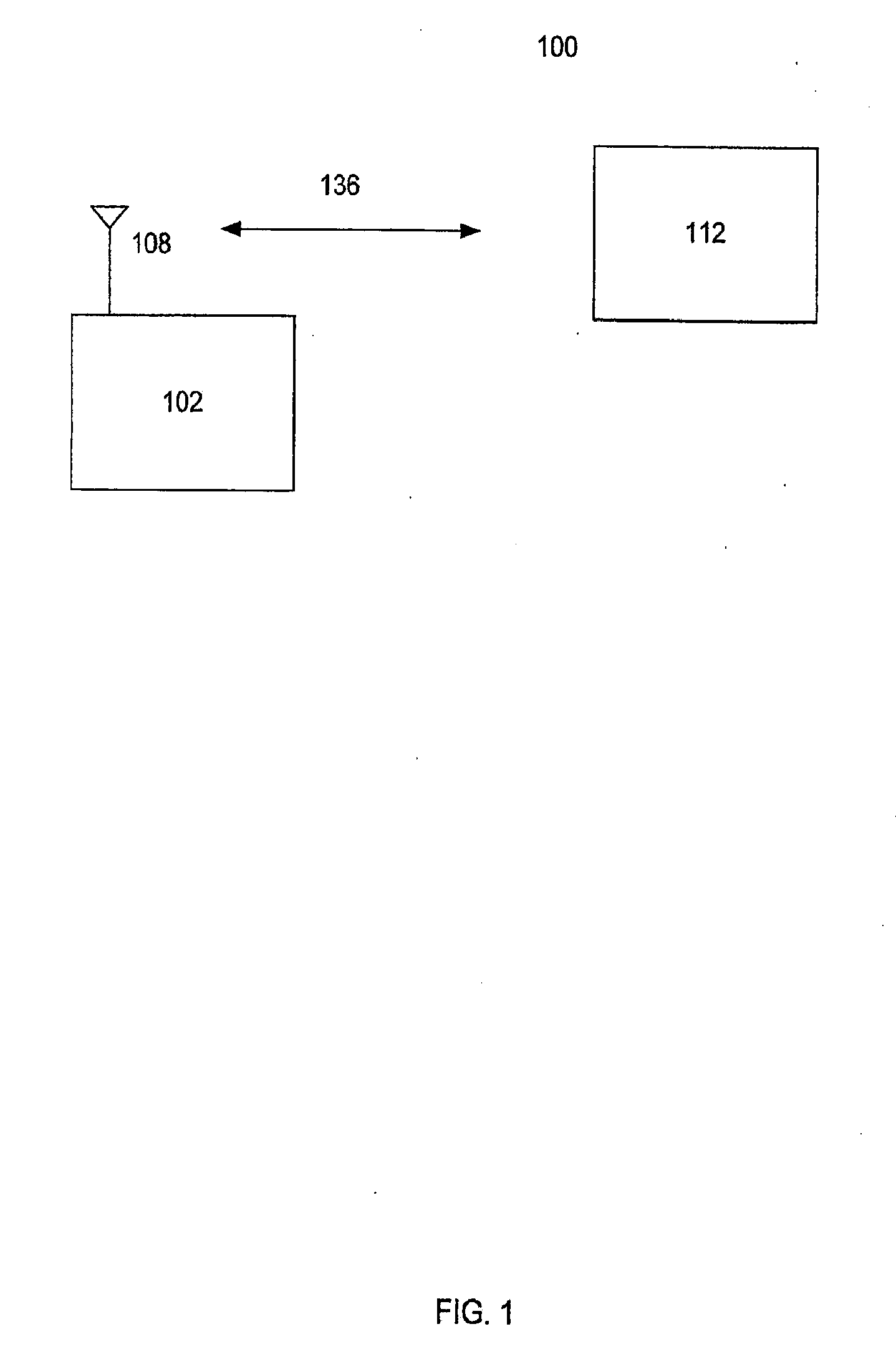
[0011]FIG. 1 is a diagram illustrating an exemplary RFID system;

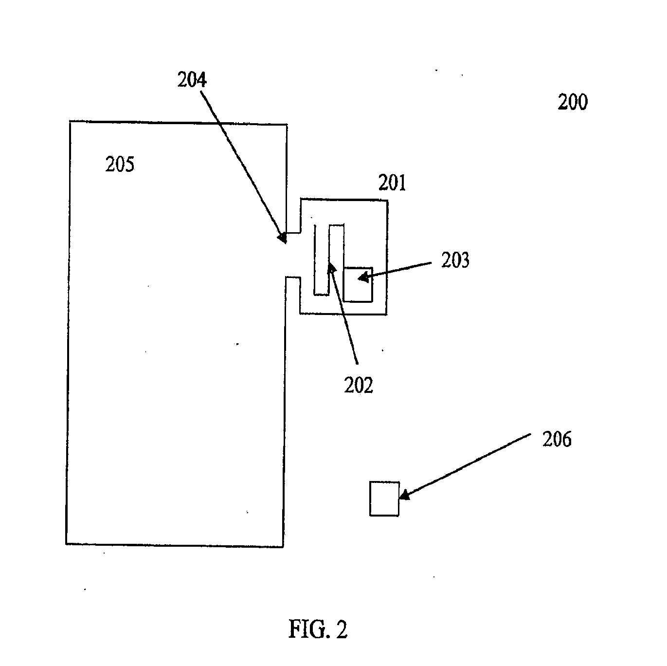
[0012]FIG. 2 is a diagram illustrating an example printed circuit board comprising a breakaway RFID tag in accordance with one embodiment of the inventor;

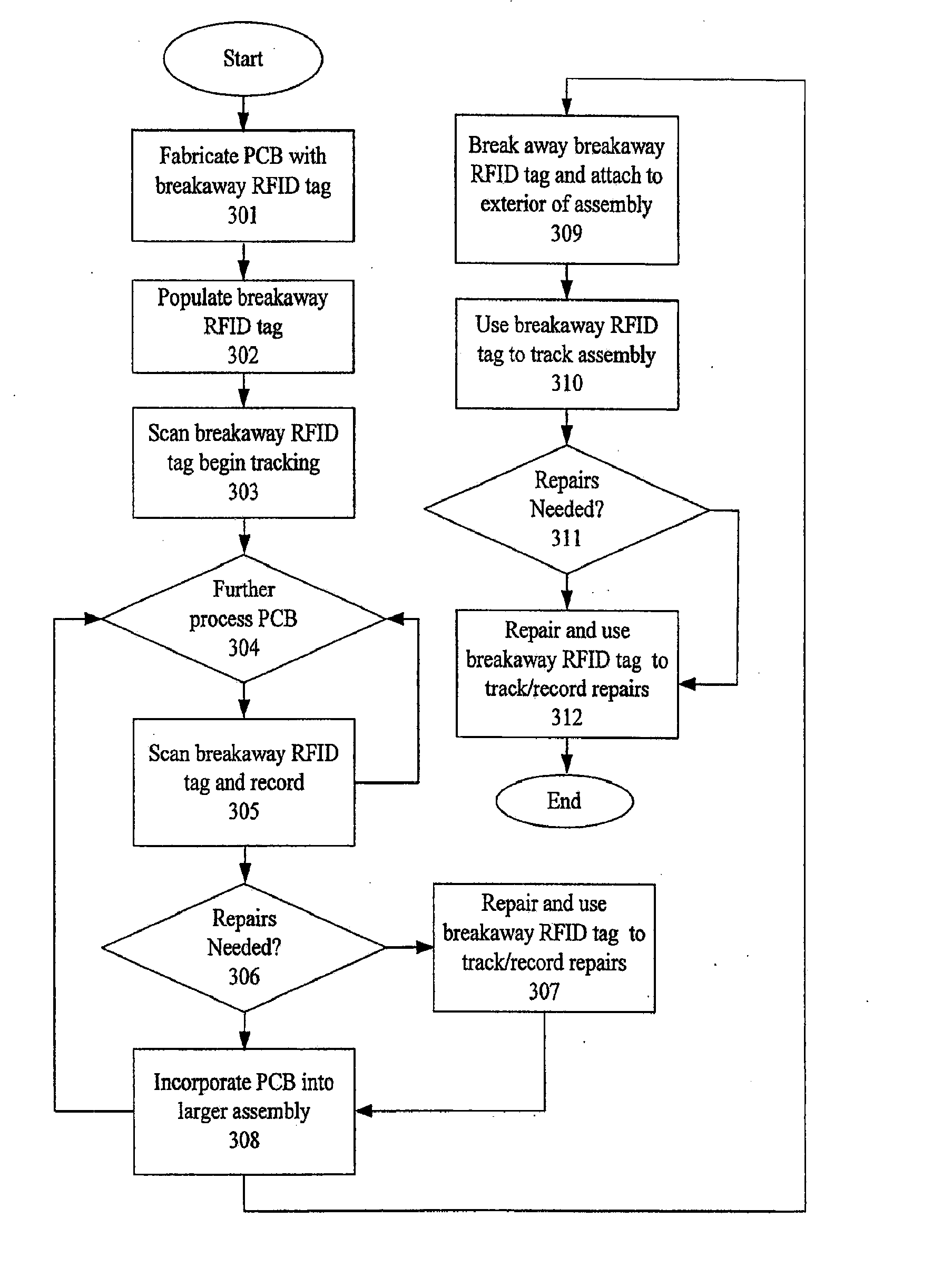
[0013]FIG. 3 is a diagram illustrating an example method for tracking an assembly process using the breakaway RFID tag of FIG. 2 in accordance with one embodiment of the invention;

[0014]FIG. 4 is a diagram illustrating an example of assembly process for the printed circuit board of FIG. 2; and,

[0015]FIG. 5 is a diagram illustrating a method of troubleshooting an assembly process using information retrieved from the breakaway RFID tag of FIG. 2.

DETAILED DESCRIPTION

[0016]FIG. 1 is a diagram illustrating an exemplary RFID system 100. As can be seen RFID system 100 comprises an RFID interrogator 102, an ...


PUM


Abstract

A breakaway RFID tag is configured such that it comprises part of a Printed Circuit Board Assembly (PCB). Thus, the breakaway RFID tag can be used to track the PCB as it migrates through a manufacturing process. In one embodiment, the RFID tag can be assembled first and then used to track the PCB as it is populated with components and installed into larger assemblies and ultimately into the end device. Once the PCB is installed into a larger assembly or the end device, the breakaway RFID tag is configured such that it can be broken off and attached to the outside of the larger assembly or end device. In this manner, the RFID tag can be used to continue tracking the PCB all the way through the end of the manufacturing process. Accordingly, tracking information can be more efficiently correlated and used to improve inventory tracking, failure trend spotting analysis, and to improve service by providing information that can quickly identify potential problems in a failed field unit.

Description

RELATED APPLICATIONS INFORMATION [0001] This application claims priority under 35 U.S.C. 119(e) to Provisional Patent Application Ser. No. 60 / 805,423, entitled “An RFID Smart Cabinet and a Multi-Document Read Write Station,” filed Jun. 21, 2006, which is incorporated herein by reference as if set forth in full.BACKGROUND [0002] 1. Field of the Invention [0003] The field of the invention relates generally to Radio Frequency Identification (RFID) systems and more particularly to the design and construction of RFID tags used for tracking the assembly of various devices. [0004] 2. Background of the Invention [0005] In complex manufacturing processes, such as the manufacturing of consumer electronics, hundreds or even thousands of parts are assembled to make a single device. It is important to track these components as they go through the manufacturing process. Often logs are used to track components using some form of serial number as they go through the manufacturing process; however, ...

Claims


Application Information

Patent Timeline
Patent Type & Authority Applications(United States)
IPC IPC(8): G08B13/14
CPCG06K7/0008G06K19/07796G06K7/10029G06Q10/08G06K19/0723H04J3/0641G06K19/07798H05K1/0268H05K1/0266H05K1/142H05K3/30G06K7/10039H05K1/02H05K2201/0909H05K2201/09127G06K7/10475
Inventor ELIZONDO, PAULAZEVEDO, JOHN
Owner SMARTRAC TECH FLETCHER INC
Learn More