Force-based input device having an elevated contacting surface

a technology of input device and contacting surface, which is applied in the field of input device, can solve the problems of lowering display contrast, difficult to use such devices in high-brightness applications, and each of the prior related types of input device, as currently configured, to achieve the effect of facilitating the determination of a location

Inactive Publication Date: 2008-02-07
QSI CORPORATION
View PDF99 Cites 46 Cited by
  • Summary
  • Abstract
  • Description
  • Claims
  • Application Information

AI Technical Summary

Benefits of technology

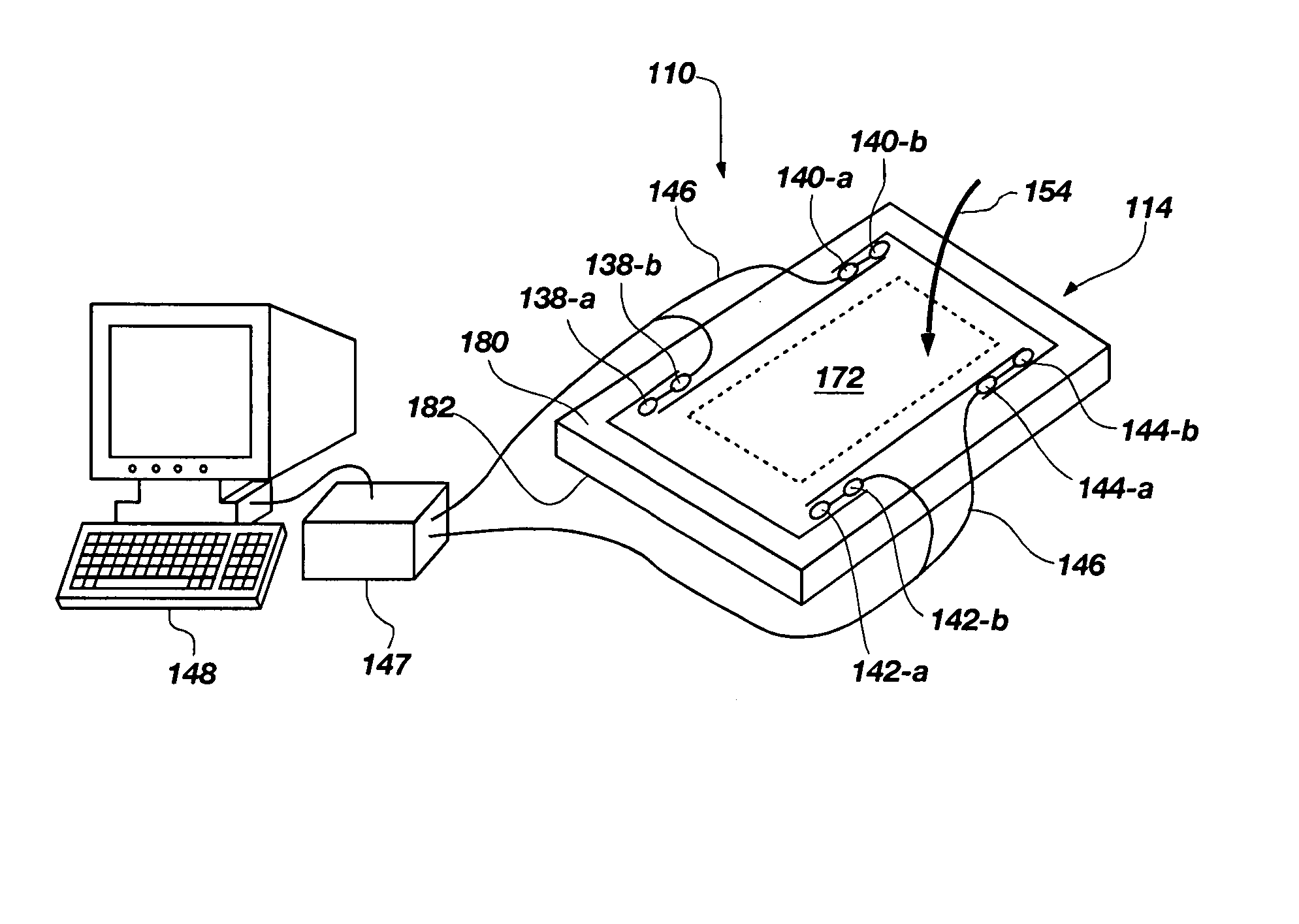
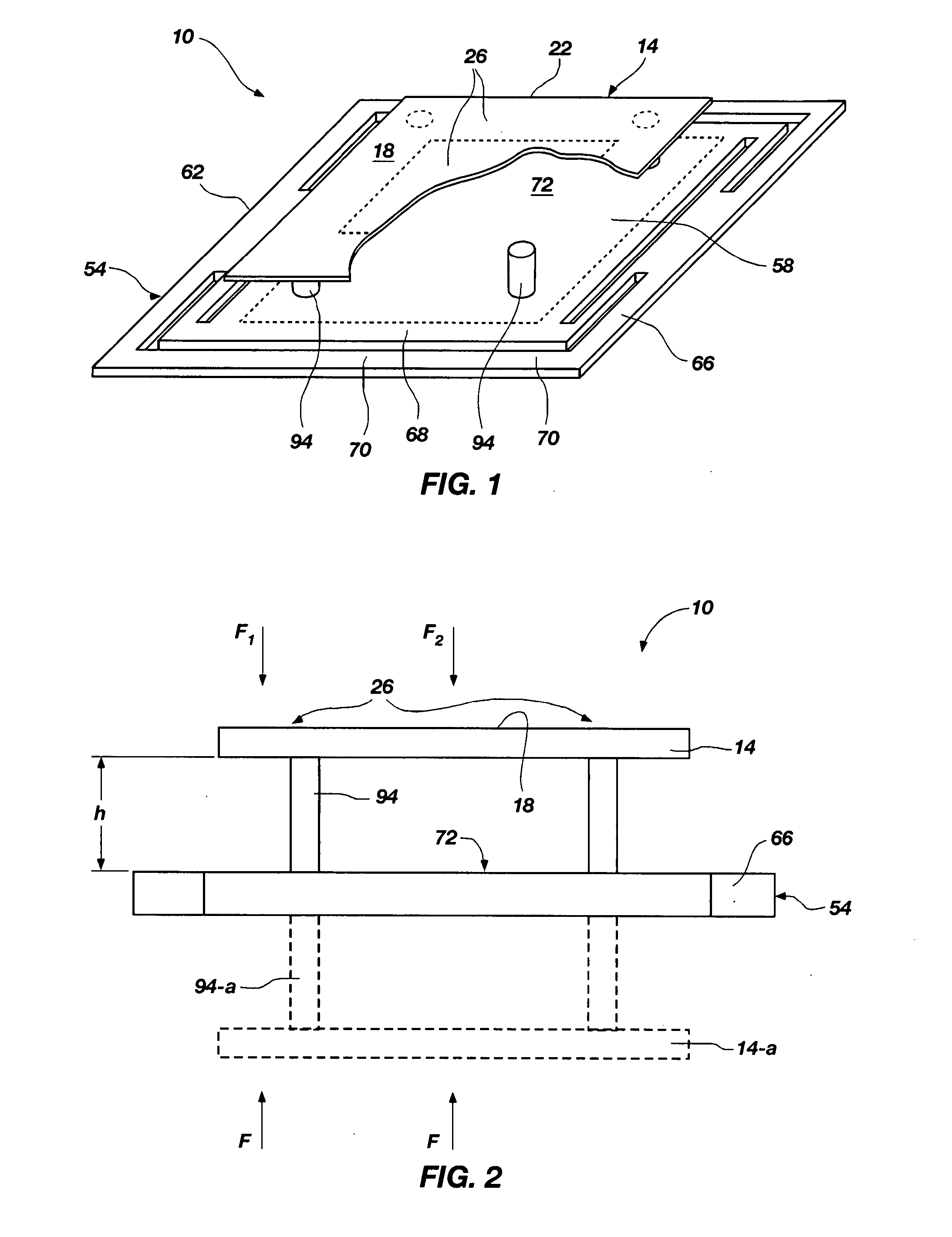
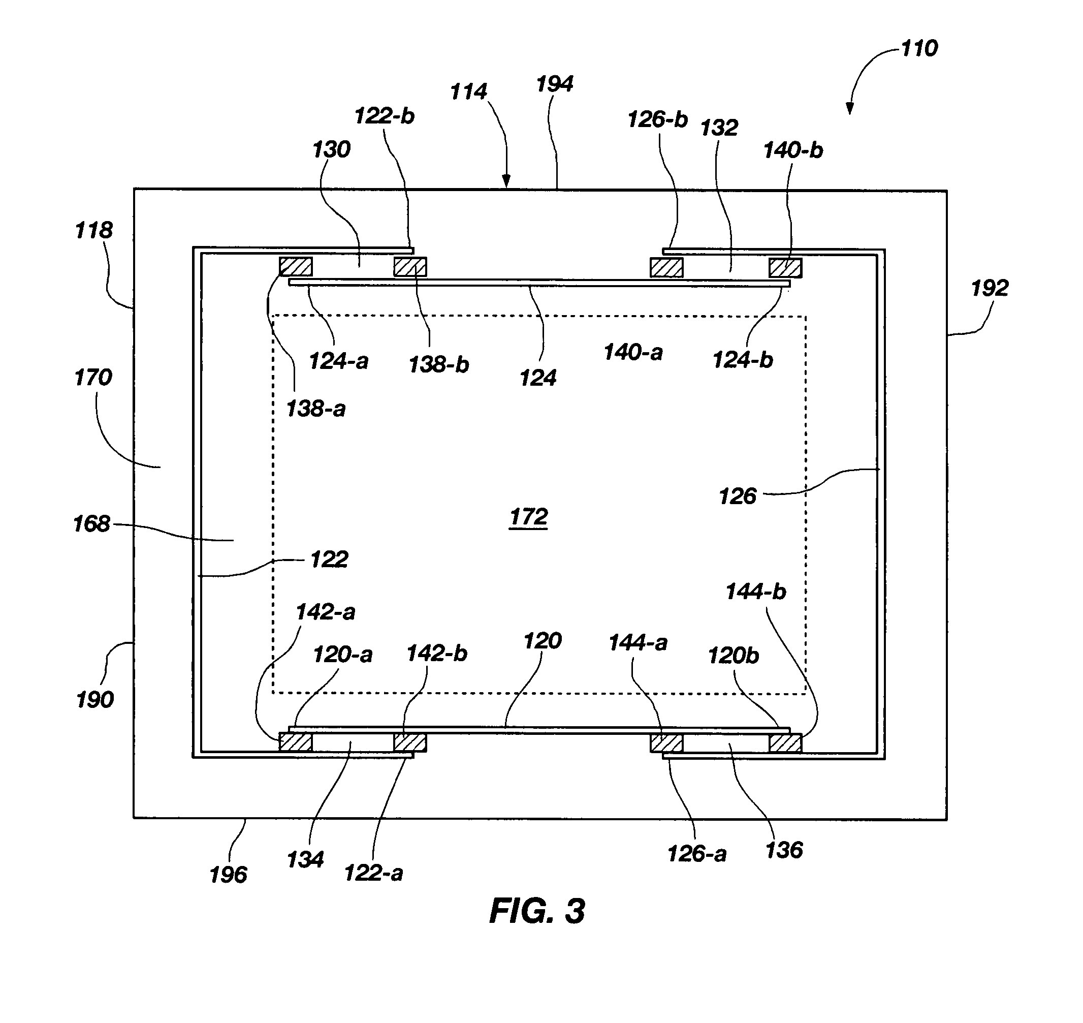
[0015] In accordance with the invention as embodied and broadly described herein, the present invention features a projected force-based input device comprising a projected or elevated contacting element configured to receive an applied force, a sensing element located in a different plane with respect to the contacting element, and a sensing portion operably supported to displace in response to the applied force. The sensing element further comprises a plurality of sensors operable to output sensor data corresponding to the applied force, wherein the sensor data facilitates the determination of a location of the applied force occurring about the contacting element, as well as the profile of the applied force over time (e.g., waveform), otherwise known as the force profile. One or more transfer elements may also be present, which function to relate the contacting element to the sensing portion of the sensing element so as to transfer substantially all of the applied force from the contacting element to the sensing element. Adequate rigidity between the elevated contacting element, and transfer elements, and the sensing element is intended to be maintained in order to prevent interference with any mounting or other structures or objects, and to permit the input device to operate properly.

Problems solved by technology

While providing some useful functional aspects, each of these prior related types of input devices, as currently configured, suffer in one or more areas.
Resistive sensors only allow transmission of about 75% of the light from the input pad, and lowering the display contrast, thereby making it difficult to use such devices in high-brightness applications.
In addition, the front layer of such devices is typically comprised of a soft material, such as polyester, that can be easily damaged by hard or sharp objects, such as car keys, pens, etc.
As such, this makes them inappropriate for most public-access applications.
Capacitance-based sensors typically are only capable of detecting large objects as these provide a sufficient capacitance to ground ratio.
In other words, capacitance-based sensors typically are only capable of registering or detecting application of an object having suitable conductive properties, thereby eliminating a wide variety of potential useful applications, such as the ability to detect styli and other similar touch or force application objects.
However, surface acoustic wave-based input devices are incapable of registering or detecting the application of hard and small objects, such as pen tips, and they are usually the most expensive of all the types of input devices.
In addition, their accuracy and functionality is affected by surface contamination, such as water droplets.
However, these are sensitive to debris, such as dirt, as well as sun or other light, all of which affect their accuracy.
Despite their advantages, existing force-based input devices are typically too large and bulky to be used effectively in many touch screen applications.
Additionally, conventional force-based input devices, as well as most other types of input devices, are capable of registering touch from only one direction, or in other words, on one side of the input pad, thereby limiting the force-based input device to monitor or screen-type applications.
One particular problem associated with force-based input devices deals with off-axis forces, which may be described as forces that are parallel to the touch surface or input portion.
These are undesirable and tend to skew any results.
However, these are difficult and costly to make, and still do not work particularly well.
Another issue facing force-based input devices is constraint or over constraint of the input member as it is often necessary to resolve the both the direction and location of application of the force.
Still another issue is vibration, which causes a problem because of the typical mass of the input member (e.g., the touch screen).
Forces may be transmitted from the support to the input member when the support experiences vibration, which may cause inaccurate measurements and readings.
These different forces have been difficult to account for.
In addition to the problems discussed above, current force-based input devices require the sensors to be located on or within the actual contacting element configured to receive the applied force.
As such, the potential applications in which such current force-based input devices may be used are limited.

Method used


Image

  • Force-based input device having an elevated contacting surface
  • Force-based input device having an elevated contacting surface
  • Force-based input device having an elevated contacting surface

Examples


Embodiment Construction

[0049] The following detailed description of exemplary embodiments of the invention makes reference to the accompanying drawings, which form a part hereof and in which are shown, by way of illustration, exemplary embodiments in which the invention may be practiced. While these exemplary embodiments are described in sufficient detail to enable those skilled in the art to practice the invention, it should be understood that other embodiments may be realized and that various changes to the invention may be made without departing from the spirit and scope of the present invention. Thus, the following more detailed description of the embodiments of the present invention is not intended to limit the scope of the invention, as claimed, but is presented for purposes of illustration only and not limitation to describe the features and characteristics of the present invention, to set forth the best mode of operation of the invention, and to sufficiently enable one skilled in the art to practi...


PUM


Abstract

A projected force-based input device comprising a projected or elevated contacting element configured to receive an applied force, a sensing element located in a different plane with respect to the contacting element, and a sensing portion operably supported to displace in response to the applied force. The sensing element further comprises a plurality of sensors operable to output sensor data corresponding to the applied force, wherein the sensor data facilitates the determination of a location of the applied force occurring about the contacting element, as well as the profile of the applied force over time (e.g., waveform), otherwise known as the force profile. One or more transfer elements may also be present, which function to relate the contacting element to the sensing portion of the sensing element so as to transfer substantially all of the applied force from the contacting element to the sensing element. Adequate rigidity between the elevated contacting element, and transfer elements, and the sensing element is intended to be maintained in order to prevent interference with any mounting or other structures or objects, and to permit the input device to operate properly.

Description

RELATED APPLICATIONS [0001] This application claims the benefit of U.S. Provisional Patent Application No. 60 / 834,663, filed Jul. 31, 2006, and entitled, “Projected Force-based Input Device,” which is incorporated by reference in its entirety herein.FIELD OF THE INVENTION [0002] The present invention relates generally to input devices, such as touch panels, touch screens, etc., and more particularly to force-based input devices of the same. BACKGROUND OF THE INVENTION AND RELATED ART [0003] Input devices (e.g., touch screens or touch pads) are designed to detect the application of an object and to determine one or more specific characteristics of or relating to the object as relating to the input device, such as the location of the object acting on the input device, the magnitude of force transmitted to the input device as induced by the object, the profile of an applied force over time (e.g., waveform), and / or a combination of these, etc. Examples of some of the different applicati...

Claims


Application Information

Patent Timeline
Patent Type & Authority Applications(United States)
IPC IPC(8): G06F3/041
CPCG06F3/0414G06F3/04142
Inventor ELWELL, JAMES K.MULLINS, JAMES R.SOSS, DAVID A.STANLEY, KAREN
Owner QSI CORPORATION
Why Eureka
Try Eureka