Magnetoresistive effect element, thin-film magnetic head, method for manufacturing magnetoresistive effect element, and method for manufacturing thin-film magnetic head

a technology of magnetoresistive effect and magnetic head, which is applied in the direction of nanomagnetism, data recording, instruments, etc., can solve the problems of inability to improve the the degradation mode becomes a problem, and the under and over layers are inevitably thin, so as to achieve sufficient bias magnetic field, sufficient crystallinity of the end portion of the magnetic domain controlling bias layer, and the effect o

Inactive Publication Date: 2008-02-07
TDK CORPARATION
View PDF4 Cites 13 Cited by
  • Summary
  • Abstract
  • Description
  • Claims
  • Application Information

AI Technical Summary

Benefits of technology

[0025]The magnetic domain controlling bias layer at least partially including an hcp structure is formed, and the single metal layer is formed of a material having a bcc structure on the magnetic domain controlling bias layer and the MR multilayered structure to cover them. Accordingly, a sufficiently thick metal layer of a material having the bcc is present on the end portion of the magnetic domain controlling bias layer that is near the MR multilayered structure and therefore especially the crystallinity of that portion of the magnetic d

Problems solved by technology

A degradation mode becomes a problem of the GMR thin-film magnetic heads and TMR thin-film magnetic heads that is capable of coping with high recording densities, and have the CPP structure.
One cause of the degradation is imperfection of the crystallinity of a magnetic domain controlling bias layer that aligns magnetic domain of a magnetization free layer of TMR read head elements or GMR read head elements with the CPP structure.
However, both of the under and over layers under and over the end portion of

Method used


Image

  • Magnetoresistive effect element, thin-film magnetic head, method for manufacturing magnetoresistive effect element, and method for manufacturing thin-film magnetic head
  • Magnetoresistive effect element, thin-film magnetic head, method for manufacturing magnetoresistive effect element, and method for manufacturing thin-film magnetic head
  • Magnetoresistive effect element, thin-film magnetic head, method for manufacturing magnetoresistive effect element, and method for manufacturing thin-film magnetic head

Examples


Embodiment Construction

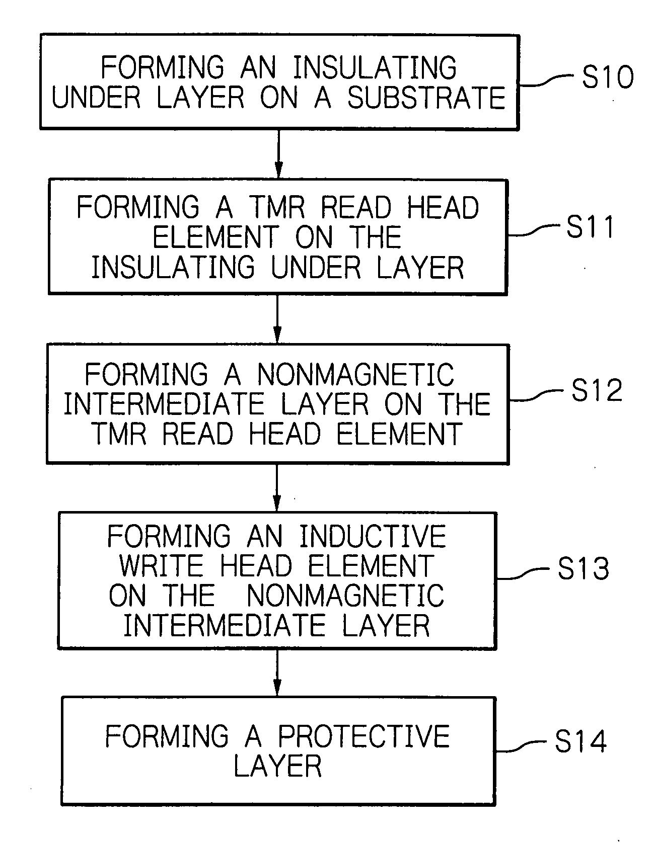
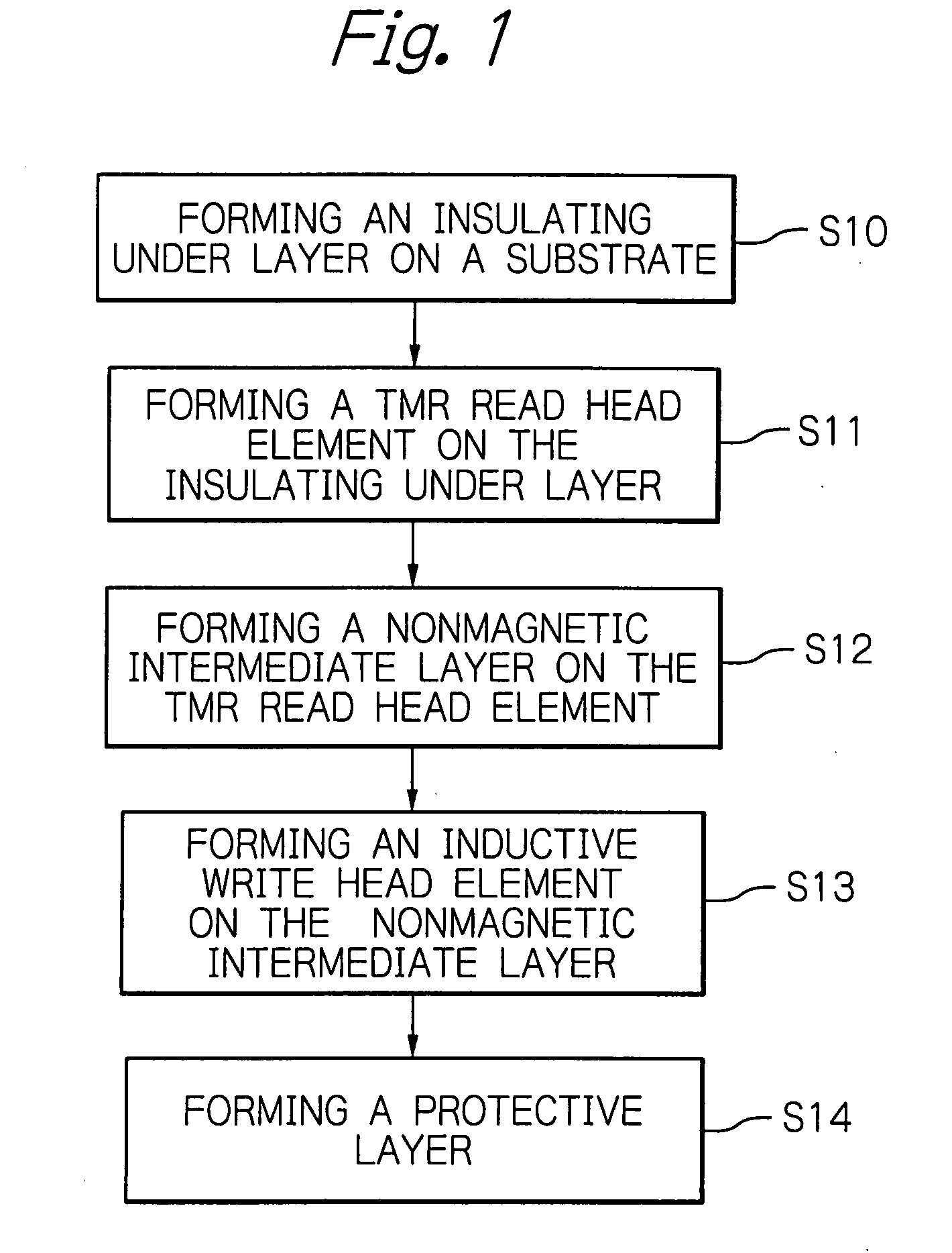
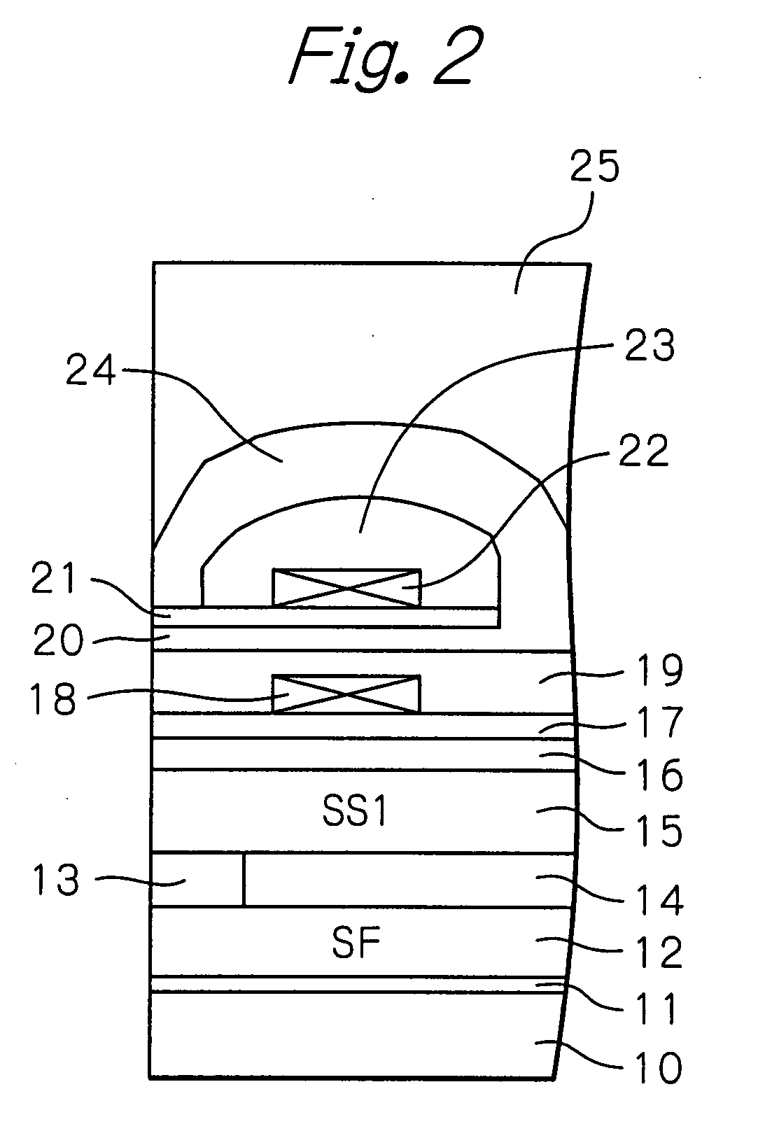
[0043]FIG. 1 is a flowchart illustrating a process for manufacturing a thin-film magnetic head according to an embodiment of the present invention, FIG. 2 is a cross-sectional view schematically showing a configuration of the thin-film magnetic head manufactured according to the embodiment shown in FIG. 1, FIG. 3 is a flowchart illustrating in detail a process for manufacturing a read head element in the manufacturing process shown in FIG. 1, and FIGS. 4a to 4c are cross-sectional views illustrating the manufacturing process shown in FIG. 3. The cross-section shown in FIG. 2 is a plane perpendicular to the ABS and the track-width direction of the thin-film magnetic head, and the cross-sections in FIGS. 4a to 4c are parallel to the ABS of the thin-film magnetic head.

[0044]While the magnetic head manufactured in this embodiment is a TMR thin-film magnetic head, a GMR thin-film magnetic head having the CPP structure can be manufactured as well using basically the same manufacturing pro...


PUM


Abstract

A magnetoresistive effect (MR) element, a thin-film magnetic head having the MR element, a method for manufacturing the MR element, and a method for manufacturing the thin-film magnetic head are disclosed. The MR element, which uses electric current in a direction perpendicular to layer planes, includes a lower electrode layer, a MR multilayered structure formed on the lower electrode layer, a magnetic domain controlling bias layer that is disposed on both sides of the MR multilayered structure along the track-width direction and is made of a material at least partially including an hcp structure, a metal layer made of a material having a bcc structure formed on the magnetic domain controlling bias layer and the MR multilayered structure to cover the magnetic domain controlling bias layer and the MR multilayered structure, and an upper electrode layer formed on the metal layer.

Description

PRIORITY CLAIM[0001]This application claims priority from Japanese patent application No. 2006-209580 filed on Aug. 1, 2006, which is incorporated herein by reference.BACKGROUND OF THE INVENTION[0002]1. Field of the Invention[0003]The present invention relates to a magnetoresistive effect (MR) element, a thin-film magnetic head having the MR element, a method for manufacturing the MR element, and a method for manufacturing a thin-film magnetic head having the MR element.[0004]2. Description of the Related Art[0005]As the recording densities of hard disk drives (HDDs) increase, highly-sensitive and high-resolution thin-film magnetic heads are being demanded. In order to meet the demand, tunnel magnetoresistive effect (TMR) thin-film magnetic heads having a TMR read head element are becoming commercially practical. TMR thin-film magnetic heads has a CPP (Current Perpendicular to Plane) structure in which sense current flows in a direction perpendicular to the film planes or layer plan...

Claims


Application Information

Patent Timeline
IPC IPC(8): G11B5/127
CPCB82Y10/00B82Y25/00G11B2005/3996G11B5/3909G11B5/3932G11B5/3906
Inventor KAGAMI, TAKEOTANAKA, KOSUKEHARA, SHINJIKANAYA, TAKAYASUMORIZUMI, NOBUYOSHI
Owner TDK CORPARATION
Why Eureka
Try Eureka