Laser beam projection mask, and laser beam machining method and laser beam machine using same

a laser beam and laser beam technology, applied in the direction of polycrystalline material growth, manufacturing tools, crystal growth process, etc., can solve the problems of structural heterogeneity in the switching characteristic of tft arrays, difficult to obtain polycrystalline silicon films with a large grain size, and difficult to obtain tfts with high electron field-effect mobility, etc., to achieve excellent crystallinity, suppress inconformity, and no crystallinity degradation

Inactive Publication Date: 2010-01-26
SHARP KK
View PDF9 Cites 1 Cited by
  • Summary
  • Abstract
  • Description
  • Claims
  • Application Information

AI Technical Summary

Benefits of technology

[0022]An object of the present invention is to provide a laser beam projection mask capable of suppressing deterioration of crystallinity attributed to inconformity between a distribution of a laser beam irradiated onto a irradiation subject and a distribution of the temperature on the irradiation subject for obtaining sufficient crystallinity, as well as a laser beam machining method and a laser beam machine using the same.

Problems solved by technology

However, as described above, the conventional ELC method involves vertical crystal growth in which crystallization occurs at random positions on the boundaries between the unmelt region and the melt region, which makes it difficult to obtain polycrystalline silicon films with a large grain size.
Because of this reason, it was difficult to obtain TFTs with high electron field-effect mobility.
Moreover, since crystallization occurs at random, such defects as structural heterogeneity among respective TFTs and heterogeneity in the switching characteristic of TFT arrays are generated.
Moreover, when these defects are generated, the TFT liquid crystal displays suffer the problem that pixels with a high display speed and pixels with a low display speed are present in one display screen.
However, the aforementioned prior art has a following problem.
Therefore, when the semiconductor element 101 is scanned by a laser beam at a high speed for expanding a crystallized region, a laser beam distribution is not necessarily congruous with a heat distribution on the surface of the semiconductor film 104, which causes the problem that a uniform crystal grain length cannot be obtained.
However, when the crystal grain length is increased with the slit having such width the problem of deteriorated crystallinity occurs.
Further, although in the prior art, a laser beam is deformed to have a homogeneous beam shape by a homogeneous optical system, complete homogenization of the laser beam causes such problems as difficulty in adjustment associated with increase in the number of optical components and degradation in efficiency.
Moreover, while there are cases of using first and second two laser beams for efficiently increasing the temperature of substrates and semiconductor materials, there is a problem that normal masks cannot cope with both the first laser beam and the second laser beam.

Method used


Image

  • Laser beam projection mask, and laser beam machining method and laser beam machine using same
  • Laser beam projection mask, and laser beam machining method and laser beam machine using same
  • Laser beam projection mask, and laser beam machining method and laser beam machine using same

Examples


first embodiment

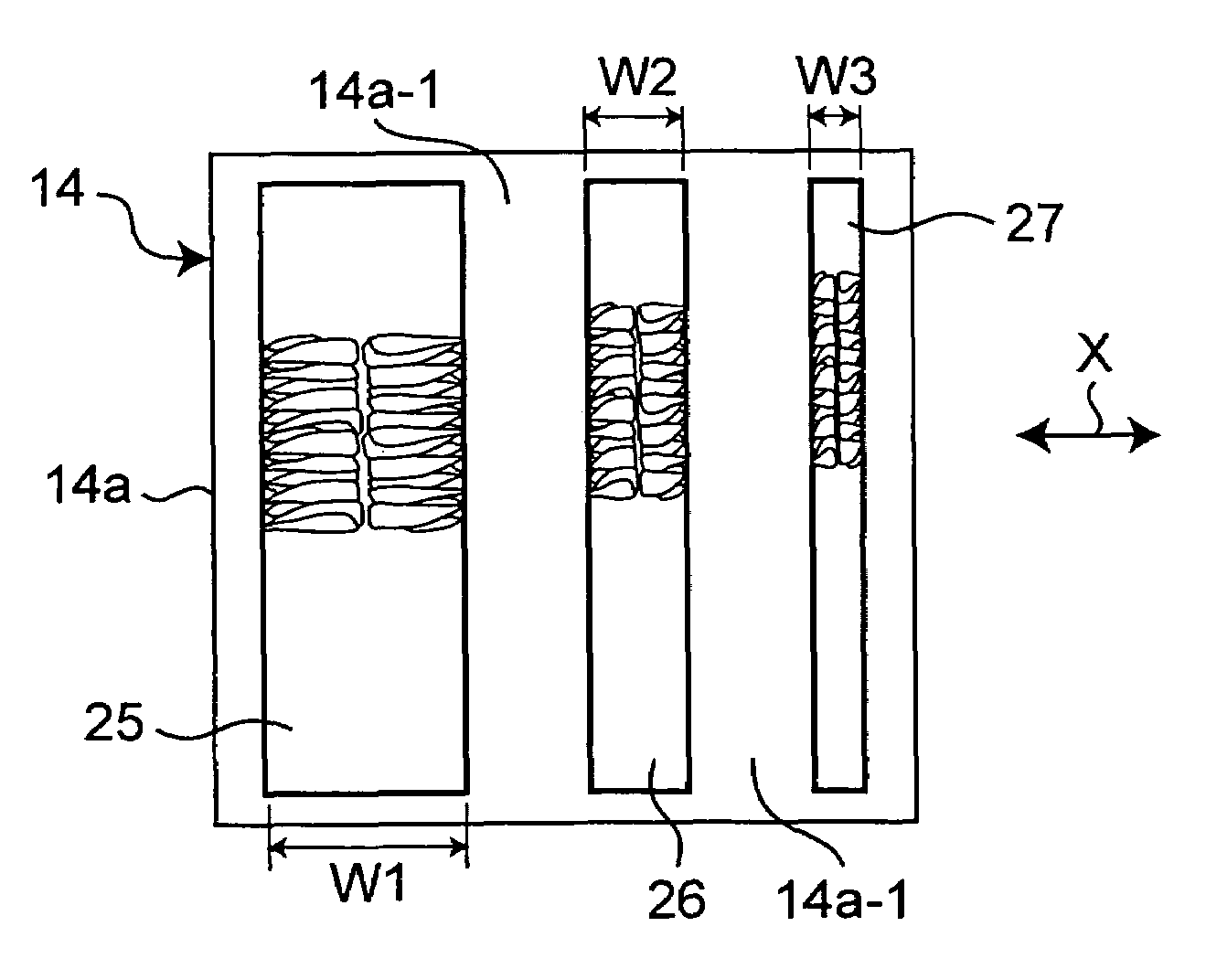
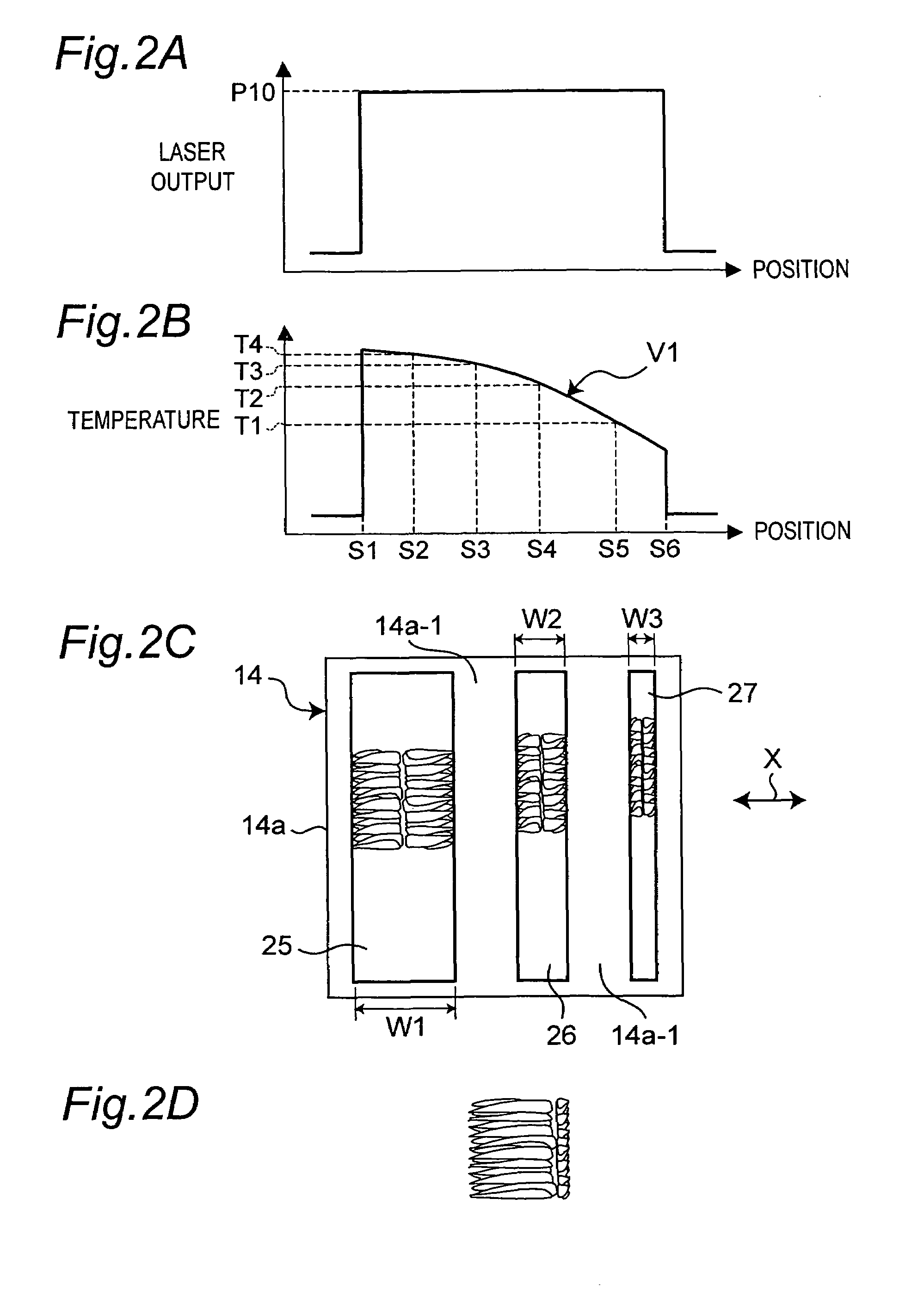
[0076]FIG. 2C shows a laser beam projection mask 14 as a first embodiment of the present invention. The laser beam projection mask 14 has three rectangular-shaped slits 25, 26, 27 as the transmission areas. A frame portion 14a of the laser beam projection mask 14 is a non-transmission area which does not transmit laser beams. These three slits 25, 26, 27 are formed in sequence in X direction shown by an arrow X in FIG. 2C at specified intervals, and the width of these slits in the X direction decreases in the order of the slit 25, the slit 26 and the slit 27.

[0077]FIG. 3 shows a laser beam machine having the laser beam projection mask 14 and a laser light source 11. The laser beam machine embodies the laser beam machine in the present invention. In the laser beam machine, a laser beam emitted from the laser light source 11 travels through a variable attenuator 12, reflection mirrors 7, 8, a varifocal field lens 13, a projection mask 14, an image-forming lens 15 and a reflection mirr...

second embodiment

[0090]Next, FIG. 5A shows a laser beam projection mask 34 as a second embodiment of the present invention. The laser beam projection mask 34 has four slits 35 to 38 formed in X direction shown in FIG. 5A at specified intervals. Moreover, three sets of the respective slits 35 to 38 are formed in Y direction orthogonal to the X direction at specified interval.

[0091]While the respective slits 35 to 38 share a size U, a size W4 of the slit 35 in Y direction is longer than a size W3 of the slit 36 in Y direction, and the size W3 of the slit 36 in Y direction is longer than a size W2 of the slit 37 in Y direction. Moreover, the size W2 of the slit 37 in Y direction is longer than a size W1 of the slit 38 in Y direction.

[0092]Moreover, as shown in FIG. 5A, the respective four slits 35 to 38 in the upper, middle and lower rows are disposed in a similar way in X direction. More particularly, the end side of the slit 36 in Y direction is displaced from the end side of the slit 35 in Y directi...

third embodiment

[0115]Next, FIG. 7 shows a laser beam projection mask 54 as a third embodiment of the present invention. The laser beam projection mask 54 has four slits 55 to 58 formed in X direction shown in FIG. 7 at specified intervals. Moreover, three sets of the respective slits 55 to 58 are formed in Y direction orthogonal to the X direction at specified interval. While the respective slits 55 to 58 share a size U11, a size W11 of the slit 55 in Y direction is shorter than a size W12 of the slit 56 in Y direction, and the size W12 of the slit 56 in Y direction is shorter than a size W13 of the slit 57 in Y direction. Moreover, the size W13 of the slit 57 in Y direction is shorter than a size W14 of the slit 58 in Y direction.

[0116]Moreover, as shown in FIG. 7, the respective four slits 55 to 58 in the upper, middle and lower rows are disposed in a similar way in X direction. More particularly, the end side of the slit 56 in Y direction is displaced from the end side of the slit 55 in Y direc...


PUM

PropertyMeasurementUnit
widthaaaaaaaaaa
lengthaaaaaaaaaa
crystal grain sizeaaaaaaaaaa

Abstract

The laser beam projection mask 14 has three rectangular-shaped slits 25, 26, 27 as transmission areas. These three slits 25, 26, 27 are formed in sequence in X direction shown by an arrow X in FIG. 2C at specified intervals, and the width in the X direction decreases in the order of the slit 25, the slit 26 and the slit 27. More particularly, transmission coefficients of the transmission areas change in conformity with a temperature distribution curve V1 of a silicon film 4 shown in FIG. 2B.

Description

CROSS-REFERENCE TO RELATED APPLICATIONS[0001]This nonprovisional application claims priority under 35 U.S.C. 119 (a) of Japanese application No. 2004-186525 filed on Jun. 24, 2004, the contents of which are fully incorporated herein by reference.BACKGROUND OF THE INVENTION[0002]The present invention relates to a laser beam projection mask, a laser beam machining method and a laser beam machine used to crystallize amorphous materials, which are for use, for example, as semiconductor materials in semiconductor devices and the like, through laser beam irradiation.[0003]While there is a method using single crystal silicon (Si) as a general manufacturing method for semiconductor devices, there is another manufacturing method, other than the manufacturing method, which uses silicon thin films produced by forming silicon thin films on glass substrates. Semiconductor devices manufactured with use of the silicon thin films formed on the glass substrates are used as part of image sensors and ...

Claims


Application Information

Patent Timeline
Patent Type & Authority Patents(United States)
IPC IPC(8): H01L21/20B23K26/066C30B13/00C30B21/04H01L21/26H01L21/268
CPCB23K26/083B23K26/066H01L21/2026H01L21/02686H01L21/0268H01L21/02691H01L21/02488H01L21/02532H01L21/26H01S3/10
Inventor NAKAYAMA, JUNICHIROSEKI, MASANORITSUNASAWA, HIROSHITANIGUCHI, YOSHIHIRO
Owner SHARP KK
Why Eureka
Try Eureka