Energy accumulation in destination nodes of wireless relay networks

a wireless relay and destination node technology, applied in data switching networks, error prevention/detection by transmission repeat, high-level techniques, etc., can solve the problems of consuming resources at each and every node, affecting the efficiency of wireless relay networks, and severely limited computation, memory and power resources in such nodes, so as to reduce the total energy consumption of the network, high probability, and efficient implementation

Inactive Publication Date: 2008-02-07
MITSUBISHI ELECTRIC RES LAB INC
View PDF8 Cites 45 Cited by
  • Summary
  • Abstract
  • Description
  • Claims
  • Application Information

AI Technical Summary

Benefits of technology

[0013]The embodiments of the invention provide a wireless network, in which relay nodes cooperate to minimize a total energy consumed in transmitting a unicast packet from a source node to a destination node. The embodiments use a progressive accumulative routing (PAR) process, which progressively performs relay discovery, relay ordering and power allocation in a distributed manner, such that each relay node only needs local information.
[0015]The PAR and DEA processes considerably reduce the total energy consumption in the network, and can be implemented efficiently. Furthermore, the processes provide optimal routing with a high probability.

Problems solved by technology

Computational, memory, and power resources in such nodes are severely limited.
Those approaches are not energy efficient, as corrupted packets are completely discarded, and of no further use.
However, those methods are designed for broadcast packets and not unicast packets.
While current and next generation wireless networks do have mechanisms in place to implement energy accumulation, doing so at each and every node consumes resources.
Because relays do not directly benefit from transmitting a packet from the source to the destination, it is difficult to justify expending significant resources for energy accumulation.
In addition, finding an optimal energy accumulative route in a wireless network with many relays nodes and jointly determining the transmit power levels of the nodes along the route is extremely difficult.
Thus, no scalable optimum mechanism is possible.

Method used


Image

  • Energy accumulation in destination nodes of wireless relay networks
  • Energy accumulation in destination nodes of wireless relay networks
  • Energy accumulation in destination nodes of wireless relay networks

Examples


Embodiment Construction

[0022]Wireless Relay Network

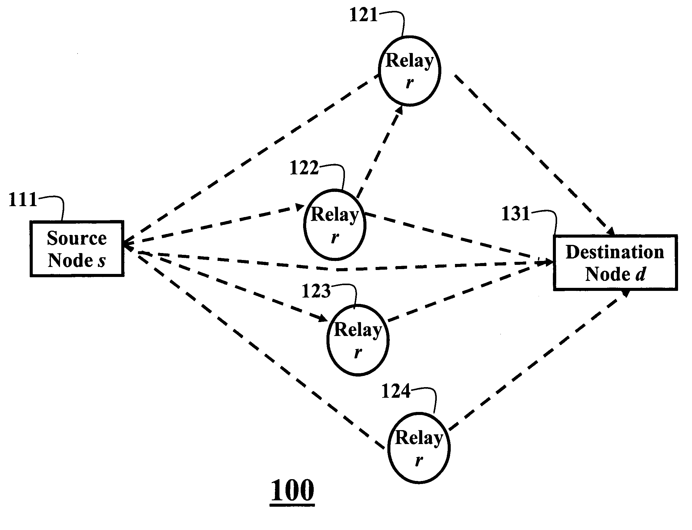
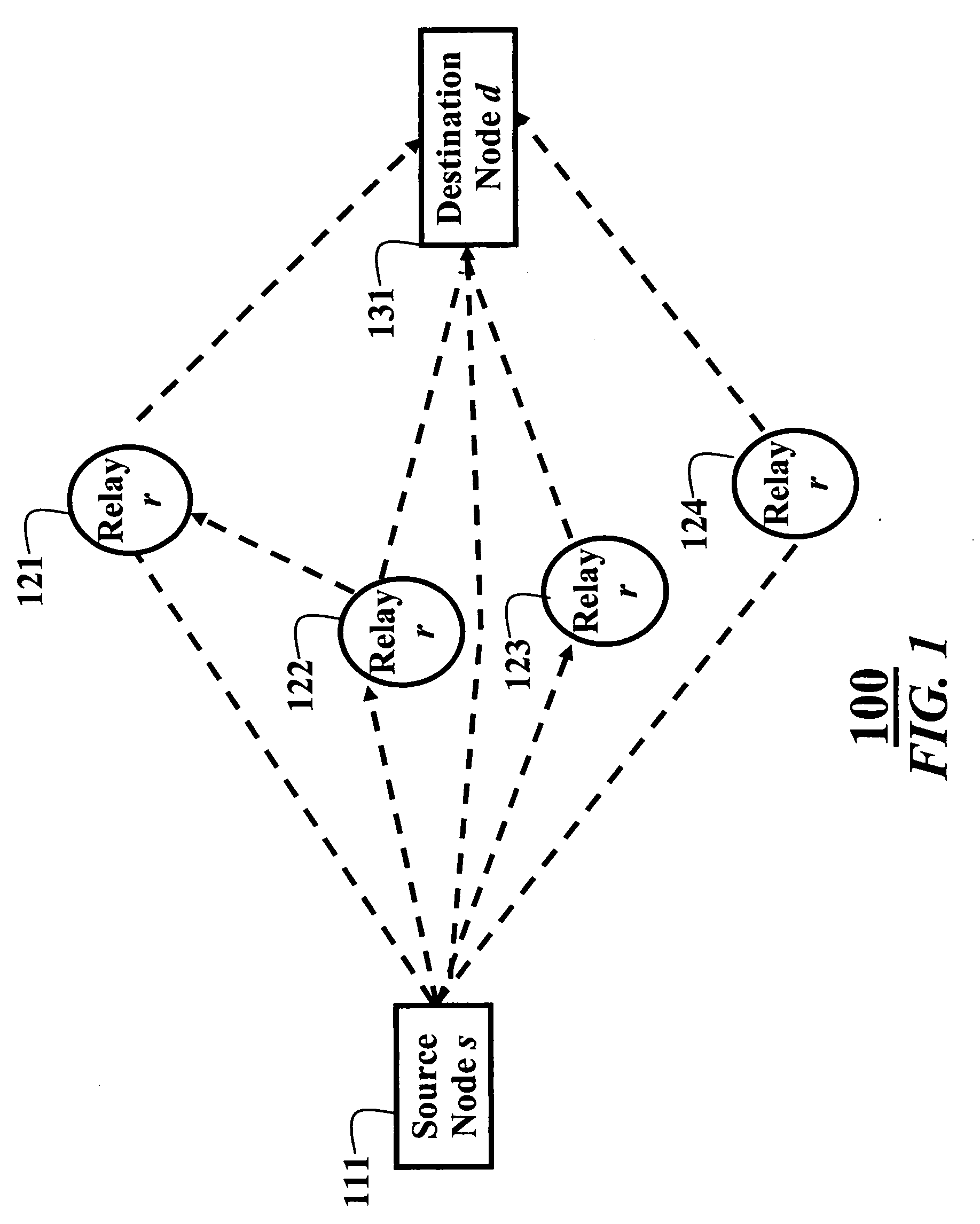
[0023]FIG. 1 shows a wireless relay network 100 according to an embodiment of our invention. The network includes a source node s 111, a destination node t 131, and one or more intermediate decode-and-forward relay nodes r 121-124. All nodes use unicast transmission via single omni-directional antennas for transmission and reception, and operate in half-duplex mode, i.e., the nodes can either transmit or receive, but not do both simultaneously. The network 100 is quasi-static, in which occasional link updates reflect possible changes of channel state information of channels of the network. The source can transmit directly to the destination, or indirectly via one or more relay nodes. The relay nodes can forward packets to the destination serially or in parallel.

[0024]Destination Energy Accumulation

[0025]The embodiments of the invention use destination energy accumulation (DEA). DEA fills the gap between the two known extremes, namely (i) a conventional ne...


PUM


Abstract

A method for transmitting packets from a source node to a destination node via relay nodes of a wireless network. Packets are transmitted from the source node, along a route of relays nodes, to the destination node in a wireless network. Energy of the packets is accumulated only in the destination node by storing multiple versions of the packet. The packets are decoded in the destination node using the accumulated energy.

Description

FIELD OF THE INVENTION[0001]This invention relates generally to wireless relay networks with multi-hop transmission of packets, and more particularly to energy accumulation in such wireless relay networks.BACKGROUND OF THE INVENTION[0002]Wireless Relay Networks[0003]In a wireless relay network, a source node transmits a packet to a destination node via relay nodes using multiple hops, i.e., a route. In many such networks, the nodes are small, low complexity sensor nodes. Computational, memory, and power resources in such nodes are severely limited. Therefore, it is important that such resources are conserved as much as possible.[0004]Multi-Hop Routing[0005]Multi-hop routing is often used in conventional wireless relay networks to reduce a total energy required to deliver a unicast packet, J. Li, D. Cordes, and J. Zhang, “Power-aware routing protocols in ad hoc wireless networks,” IEEE Wireless Commun. Magazine, pp. 69-81, December 2005, and A. Michail and A. Ephremides, “Energy effi...

Claims


Application Information

Patent Timeline
Patent Type & Authority Applications(United States)
IPC IPC(8): H04L12/56
CPCH04L1/08H04L45/24Y02B60/50H04W40/02Y02B60/42H04L2001/0096Y02D30/00Y02D30/70
Inventor MEHTA, NEELESH B.YIM, RAYMONDMOLISCH, ANDREAS F.ZHANG, JINYUN
Owner MITSUBISHI ELECTRIC RES LAB INC
Why Eureka
Try Eureka