Controlling optical signal transmission to reduce optical signal degradation

Inactive Publication Date: 2008-02-07
APPLIED OPTOELECTRONICS
View PDF7 Cites 39 Cited by
  • Summary
  • Abstract
  • Description
  • Claims
  • Application Information

AI Technical Summary

Problems solved by technology

In IEEE 802.3ah EPON networks, for example, the Ethernet (data) signal transmitted at 1490 nm amplifies any video signal transmitted at 1550 nm, and therefore interference can result in a noticeable degradation of video quality.
A particularly egregious case occurs when an Ethernet idle pattern is transmitted because no data is available to transmit.
This causes interference with broadcast video on certain channels.
SRS interference may cause the CNR of a received optical video signal to degrade to below acceptable levels for several channels of the video signal, particularly lower-frequency channels.
However, there may be limitations as to how much pre-emphasis may be applied in an optical transmitter and optical network.
Thus, this approach

Method used


Image

  • Controlling optical signal transmission to reduce optical signal degradation
  • Controlling optical signal transmission to reduce optical signal degradation
  • Controlling optical signal transmission to reduce optical signal degradation

Examples


Embodiment Construction

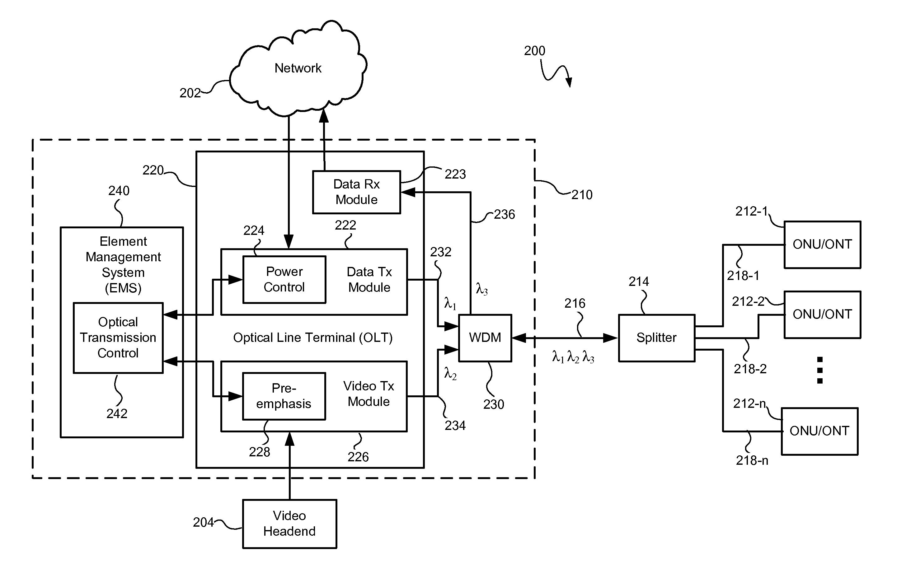
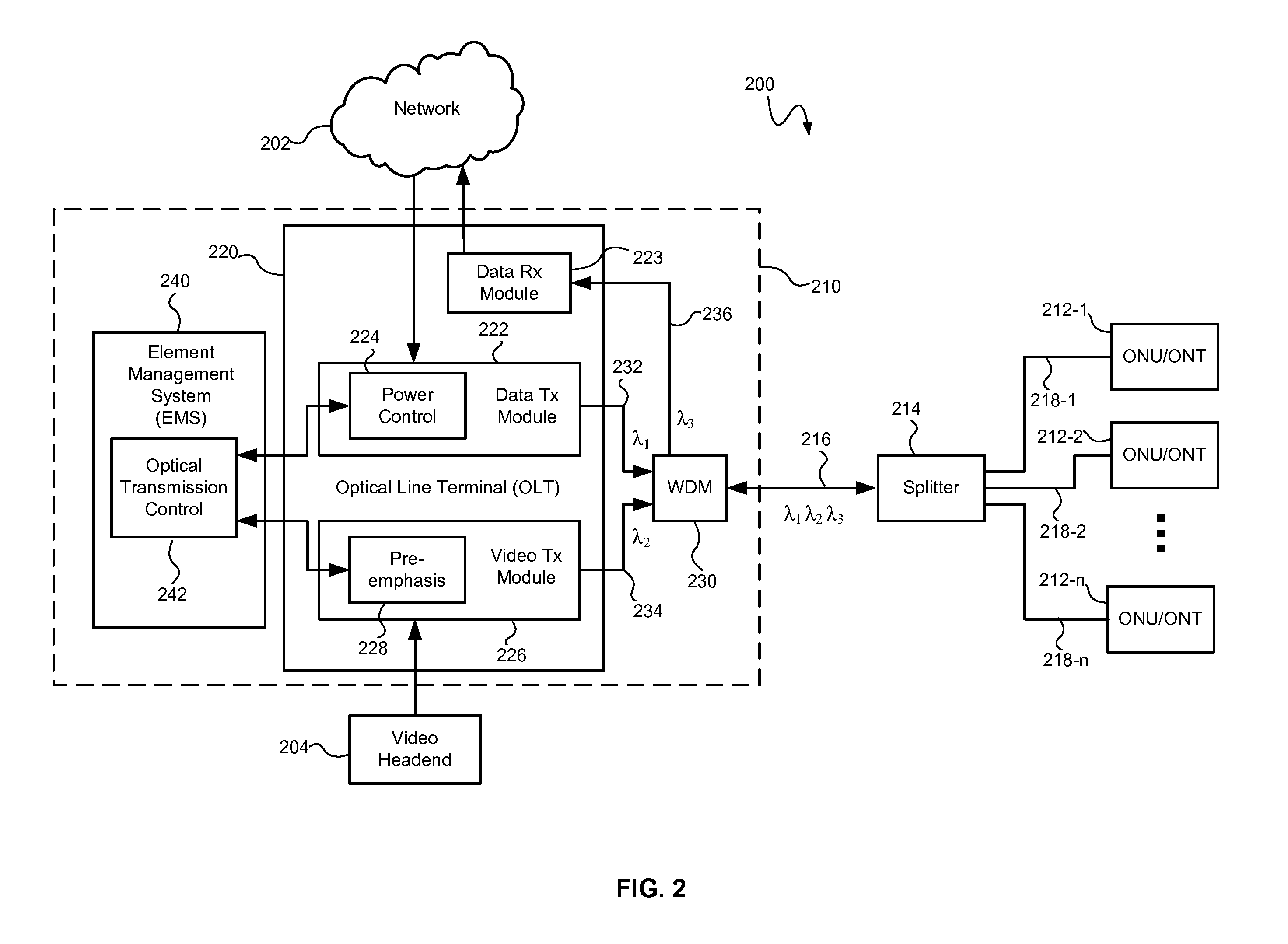
[0019] An optical transmission system and method may control optical signal transmission in an optical network to reduce degradation of one or more optical signals traveling over the same optical waveguide. In particular, optical signal transmission may be controlled to reduce carrier to noise ratio (CNR) degradation of an optical signal resulting from the effects of stimulated Raman scattering (SRS) and / or double Rayleigh backscattering (DRBS). The CNR degradation may be reduced by controlling transmission of one or more of a plurality of optical signals in the optical network based on various parameters affecting the contribution to CNR degradation by SRS and / or DRBS and affecting the performance of the optical transmission system. The parameters may include the optical wavelengths and power levels of the optical signals and the length of the optical transmission waveguides (e.g., the optical fibers). As will be described in greater detail below, optical signal transmission may be...


PUM


Abstract

An optical transmission system and method may control optical signal transmission in an optical network, such as a passive optical network (PON), to reduce degradation of one or more optical signals traveling over the same optical waveguide. In particular, optical signal transmission may be controlled to reduce carrier to noise ratio (CNR) degradation of an optical signal (e.g., a multichannel video signal) resulting from the effects of stimulated Raman scattering (SRS) and/or double Rayleigh backscattering (DRBS). The CNR degradation may be reduced by controlling transmission of one or more of a plurality of optical signals in the optical network based on various parameters affecting the contribution to CNR degradation by SRS and/or DRBS and affecting the performance of the optical transmission system. The optical signal transmission may be controlled by adjusting a preemphasis and/or transmitted power of the optical signal(s).

Description

CROSS-REFERENCE TO RELATED APPLICATIONS [0001] This application claims the benefit of U.S. Provisional Patent Application Ser. No. 60 / 820,457 filed Jul. 26, 2006, which is fully incorporated by reference.TECHNICAL FIELD [0002] The present invention relates to optical transmission systems and methods and more particularly, to an optical transmission system and method that controls optical signal transmission to reduce optical signal degradation. BACKGROUND INFORMATION [0003] Various optical networks employ lasers as sources of data transmitted over the network. Such networks include passive optical networks (PONs) such as an Ethernet-based passive optical network (EPON), an ATM-based broadband passive optical network (BPON), and an ATM-based gigabit passive optical network (GPON). Such networks may employ fiber-to-the-home and fiber-to-the-premises (FTTH / FTTP) broadband network equipment. [0004] PONs may be used to overlay a video RF signal in the optical fiber with a digital data si...

Claims


Application Information

Patent Timeline
IPC IPC(8): H04B10/08
CPCH04J14/0221H04B10/25751H04B10/2537
Inventor KUO, CHIEN-YUZHANG, WANGSHENGSHIH, YU-YUNKUO, CHAU-HONG
Owner APPLIED OPTOELECTRONICS
Why Eureka
Try Eureka