
Broadband high power light source

a high-power, light source technology, applied in lighting support devices, instruments, lighting and heating apparatuses, etc., can solve the problems of limited optical power with which fibres may be pumped, and limited optical power, so as to simplify optical design, high optical peak power, and high-power cw sources

Active Publication Date: 2014-05-20
NKT PHOTONICS
View PDF9 Cites 21 Cited by
  • Summary
  • Abstract
  • Description
  • Claims
  • Application Information

AI Technical Summary

Benefits of technology

[0040]As discussed above one advantage of the present invention is that the generator fibre is in one embodiment able to accept high optical peak power. The average optical power of the pump light depends on the peak power as well as the repetition rate and pulse duration of the individual pulses. In one embodiment the average power of the pump light injected into the input end of said generator fibre is arranged to be more than or equal to 0.1 mW, such as more than or equal to 1 mW, such as more than or equal to 50 mW, such as more than or equal to 100 mW, 150 mW, such as more than or equal to 200 mW, such as more than or equal to 250 mW, such as more than or equal to 300 mW, such as more than or equal to 350 mW, such as more than or equal to 400 mW, such as more than or equal to 500 mW, such as more than or equal to 1 W, such as more than or equal to 5 W, such as more than or equal to 10 W, such as more than or equal to 50 W, such as more than or equal to 200 W, such as more than or equal to 500 W, such as more than or equal to 1,000 W, such as more than or equal to 2,000 W, such as more than or equal to 10,000 W, such as more than or equal to 50,000 W, such as more than or equal to 100,000 W. In one embodiment the average power of the pump light injected into the input end of said generator fibre is arranged to be less than or equal to 100 kW, such as less than or equal to 50 kW, such as less than or equal to 10 kW, such as less than or equal to 5 kW, such as less than or equal to 2 kW, such as less than or equal to 1 kW, such as less than or equal to 0.5 kW, such as less than or equal to 0.2 kW, such as less than or equal to 0.1 kW, such as less than or equal to 50 W, such as less than or equal to 25 W, such as less than or equal to 10 W, such as less than or equal to 5 W, such as less than or equal to 2 W, such as less than or equal to 1 W, such as less than or equal to 500 mW, such as less than or equal to 200 mW, such as less than or equal to 100 mW, such as less than or equal to 50 mW, such as less than or equal to 25 mW, such as less than or equal to 10 mW, such as less than or equal to 5 mW, such as less than or equal to 1 mW.
[0041]In one embodiment the pump light source is arranged to inject pump light into the input end of said generator fibre where said pump light is substantially continuous wave (CW). In the case of CW light the term peak power otherwise discussed in this text is taken to refer to the average optical power of the CW light. Pumping the generator fibre using a CW source may simplify the optical design relative to a light source with a pulsed pump and some applications of the light source may benefit from a CW output. Other advantages may include cost, as high power CW sources may be cheaper pr. average power than pulsed sources. On the other hand, a pulsed pump laser may provide the same peak power as a CW pump with less average power. In one embodiment this provides for a more stabile light source and / or for a light source with a longer life time. In one embodiment a high average optical power of the pump corresponds to a high spectral density of the generated light which may or may not be desirable depending on the application of the light source.
[0043]In one embodiment the pump source is arranged to inject pulsed light where each pulse comprise a pulse energy higher than 50 μJ, such as equal to or higher than 100 μJ, such as equal to or higher than 200 μJ, such as equal to or higher than 300 μJ, such as equal to or higher than 500 μJ, such as equal to or higher than 1 mJ, such as equal to or higher than 10 mJ.
[0044]In one embodiment the output light is pulsed where each pulse comprise a pulse energy higher than 50 μJ, such as equal to or higher than 100 μJ, such as equal to or higher than 200 μJ, such as equal to or higher than 300 μJ, such as equal to or higher than 500 μJ, such as equal to or higher than 1 mJ, such as equal to or higher than 10 mJ.
[0045]In one embodiment the average peak power density of the pump light over the core is more than or equal to 100 W / (π·D2 / 4)≧1, 2 W / μm2, such as larger than or equal to 25 W / μm2, such as larger than or equal to 50 W / μm2, such as larger than or equal to 75 W / μm2, such as larger than or equal to 100 W / μm2, such as larger than or equal to 250 W / μm2, such as larger than or equal to 500 W / μm2, such as larger than or equal to 1 kW / μm2, such as larger than or equal to 10 kW / μm2, such as larger than or equal to 25 kW / μm2, such as larger than or equal to 50 kW / μm2, such as larger than or equal to 100 kW / μm2, such as larger than or equal to 250 kW / μm2. In one embodiment the average peak power density of the pump light over the core is less than or equal to 250 kW / μm2, such as less than or equal to 100 kW / μm2, such as less than or equal to 10 kW / μm2, such as less than or equal to 1 kW / μm2, such as less than or equal to 500 W / μm2, such as less than or equal to 250 W / μm2, such as less than or equal to 100 W / μm2, such as less than or equal to 50 W / μm2, such as less than or equal to 10 W / μm2, such as less than or equal to 1 W / μm2.

Problems solved by technology

This limits the optical power with which the fibre may be pumped either due to the damage threshold of the end facet of the fibre or the damage threshold of the fibre core.
The optical power may also be limited by the availability or cost of a high power laser having an output with a sufficient beam quality to allow a substantial amount of its output to enter the fibre.

Method used


Image

  • Broadband high power light source
  • Broadband high power light source
  • Broadband high power light source

Examples


example 1

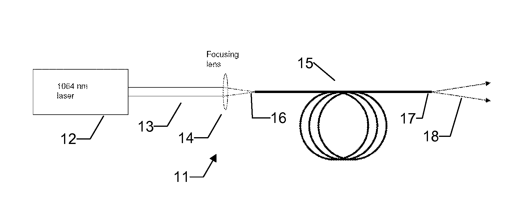
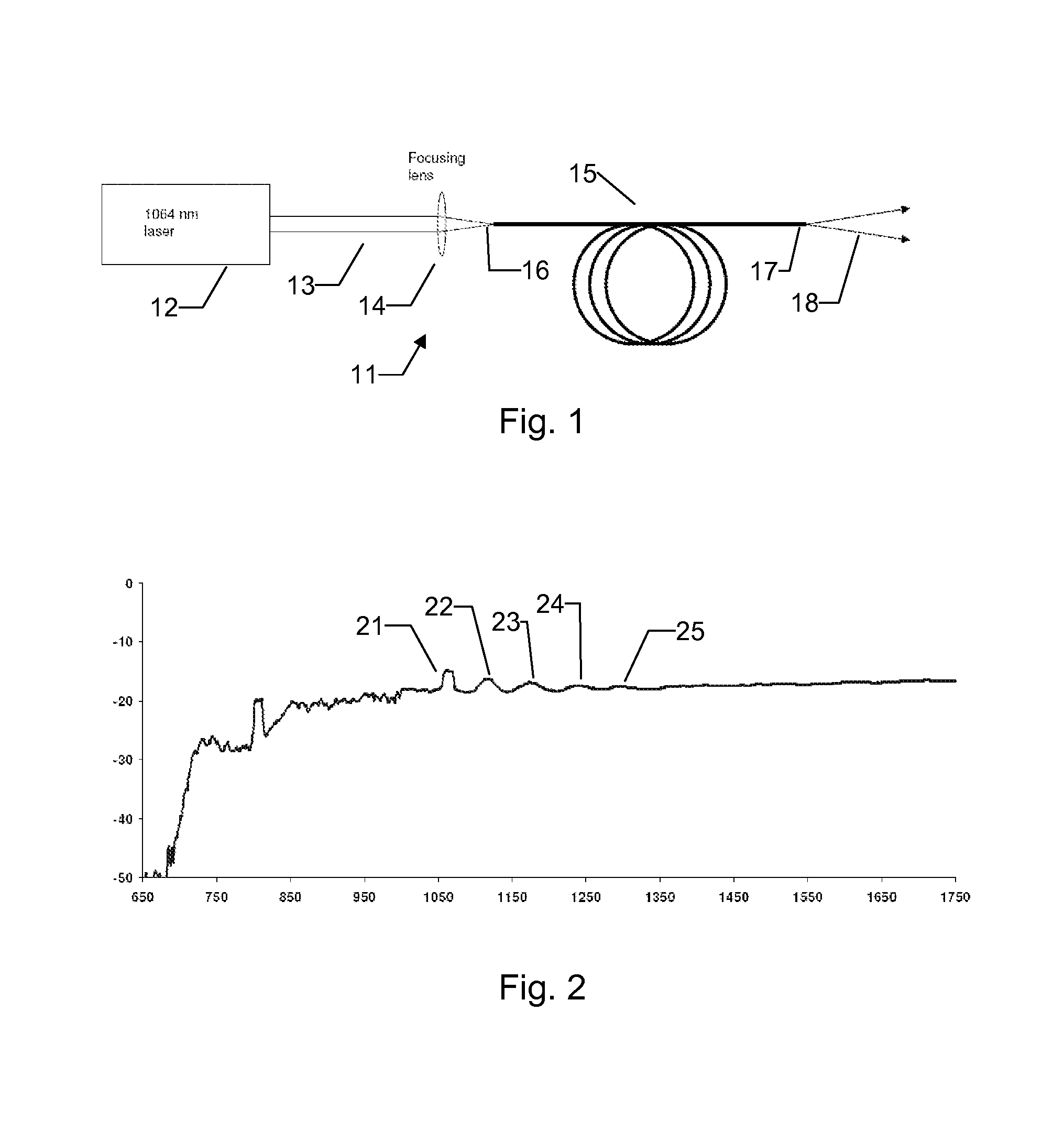
[0073]FIG. 1 show a schematic outline of a super continuum light source 11 according to the invention. The pump source 12 emits a pump beam 13 which is focused onto the input end 16 of the generator fibre 15 via a lens 14. At the output end 17 of the generator fibre 15 the output light 18 is emitted. In one embodiment the output light is substantially single mode at least for most wavelengths of the generated SC as discussed above. An exemplary spectrum of the output light of a light source according to the invention is shown in FIG. 2. Here a commercially available fibre (Infinicor of Corning Inc, Corning N.Y., USA) is applied as generator fibre 15. This fibre is a graded index fibre having a substantially parabolic index profile with a quoted core size with a diameter of 50 μm. The generator fibre 15 is pumped by a pulsed laser at 1064 nm at relatively high peak power (˜200 uJ pulse energy, ˜2 ns pulse, ˜100 kW peak power and M2 of about 2). The residual power from the pump light ...

example 2

[0074]In this example the light source is identical to that of example 1 except that the pump source inject pump light at 1064 nm and 532 nm simultaneously. In one embodiment Raman shifted light originating from the 532 nm pump merges with the short wavelength light generated from the 1064 nm pump thus providing a continuum with greater spectral width. In this way a source may be provided which provides a larger portion of energy in the visible range.

example 3

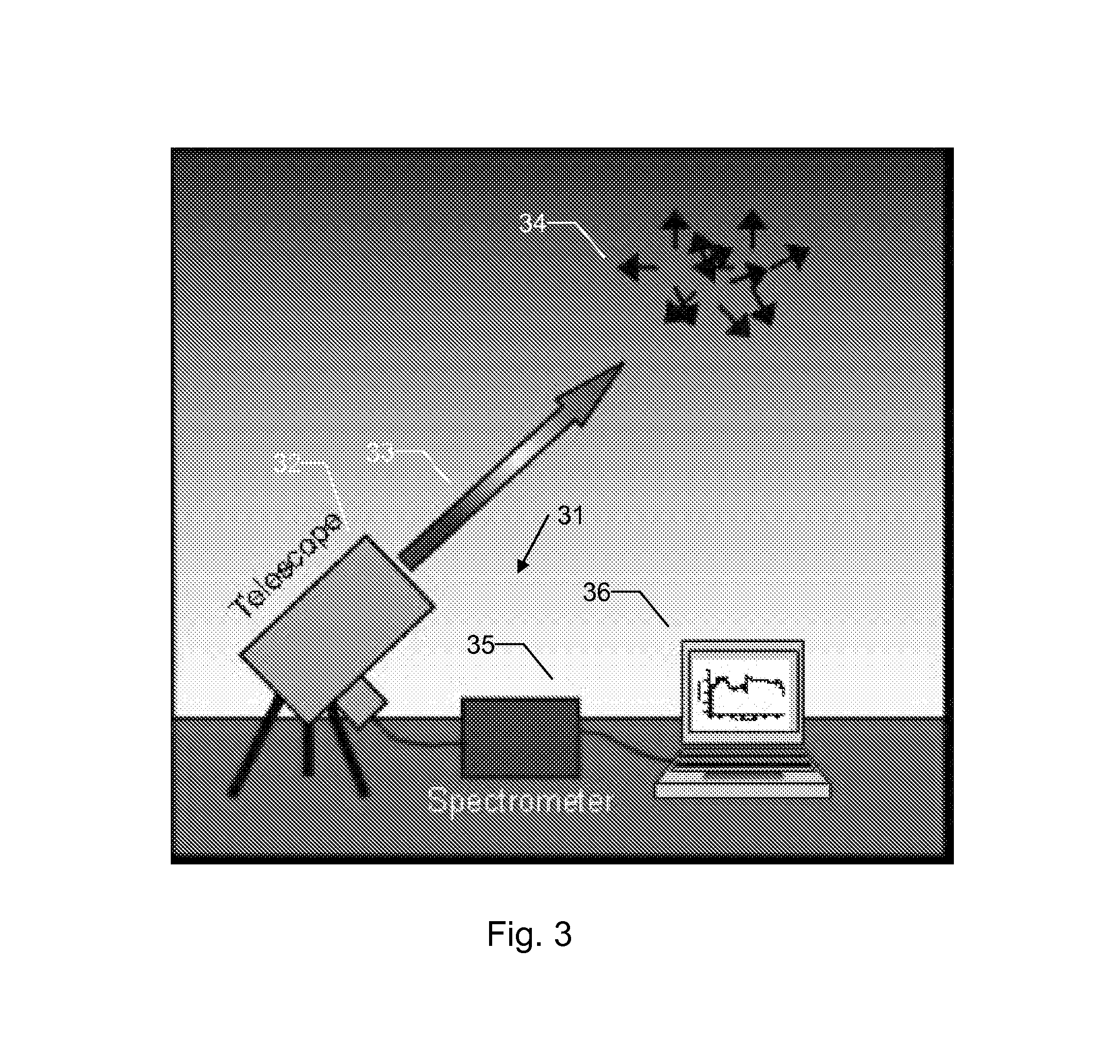
[0075]FIG. 3 shows a schematic depiction of a light source according to the invention applied in a LIDAR system 31. A telescope 32 comprising a light source according to the invention emits a SC beam 33 and detects reflected light from aerosols 34 in the atmosphere. The reflected light is analysed in a spectrometer 35 and results are relayed to a computer 36. Due to the high optical power which may be provided by an embodiment of the invention the signal-to-noise ratio (SNR) may be improved which may effectively extend the range of the system and / or allow for detection of smaller amounts of aerosols. Similarly to this example the system may instead be configured as a transmission system where the light beam is directed towards a detector. Such a system is also sometimes referred to as a DOAS system.

[0076]The present invention may also be applied as a light source in so called active hyperspectral imaging where the increased power and / or good beam quality which may be provided with t...


PUM


Abstract

The present invention relates to a super continuum light source comprising a pump source arranged to emit light having a center wavelength λcenter arranged to provide pump pulse to a generator fiber, where the refractive index profile of the core is arranged to allow modal cleaning of the light is it propagates, such as via stimulated Raman scattering. An example of invention is the application of a relatively high power pump laser utilized to provide an optical super continuum with relatively high spectral density and / or good beam quality even though the pump laser may provide a beam with a high M2.

Description

FIELD OF INVENTION[0001]The present invention relates to a super continuum light source comprising a pump source arranged to emit light having a centre wavelength λcentre and a spectral width Δλ, the light source further comprising a generator fibre, said generator fibre having an input end and an output end, the latter being arranged to emit an optical super continuum when the light source is in use.BACKGROUND ART[0002]Super continuum (SC) generation is a nonlinear phenomenon characterised by dramatic spectral broadening of intense light passing through a nonlinear material. SC generation occurs in various media and may find use in numerous applications such as spectroscopy or ultra-short-pulse generation. Spectral slicing of a generated SC is an elegant way of replacing multiple light sources having separate wavelengths.[0003]Many prior art SC light sources are based on micro structured fibres (MF) which posses unique optical properties with a large degree of freedom of design thu...

Claims


Application Information

Patent Timeline
Patent Type & Authority Patents(United States)
IPC IPC(8): H01S3/30
CPCG02F1/365G02F1/3528H01S3/30H01S3/067H01S3/302
Inventor BUCHTER, SCOTT CHARLES
Owner NKT PHOTONICS
Learn More