Supercharge Your Innovation With Domain-Expert AI Agents!

Configurable blade enclosure

a blade enclosure and configuration technology, applied in the field of blade technology, can solve the problems of increasing the complexity of the system, raising the risk of misconnection, and the cabling runs contrary to the philosophy and goals of the blade enclosur

Inactive Publication Date: 2008-02-07
IBM CORP
View PDF7 Cites 8 Cited by
  • Summary
  • Abstract
  • Description
  • Claims
  • Application Information

AI Technical Summary

Problems solved by technology

And, in addition to increasing the complexity of the system and raising the risk of misconnections, cabling runs contrary to the philosophy and goals of a blade enclosure.

Method used


Image

  • Configurable blade enclosure
  • Configurable blade enclosure
  • Configurable blade enclosure

Examples


Embodiment Construction

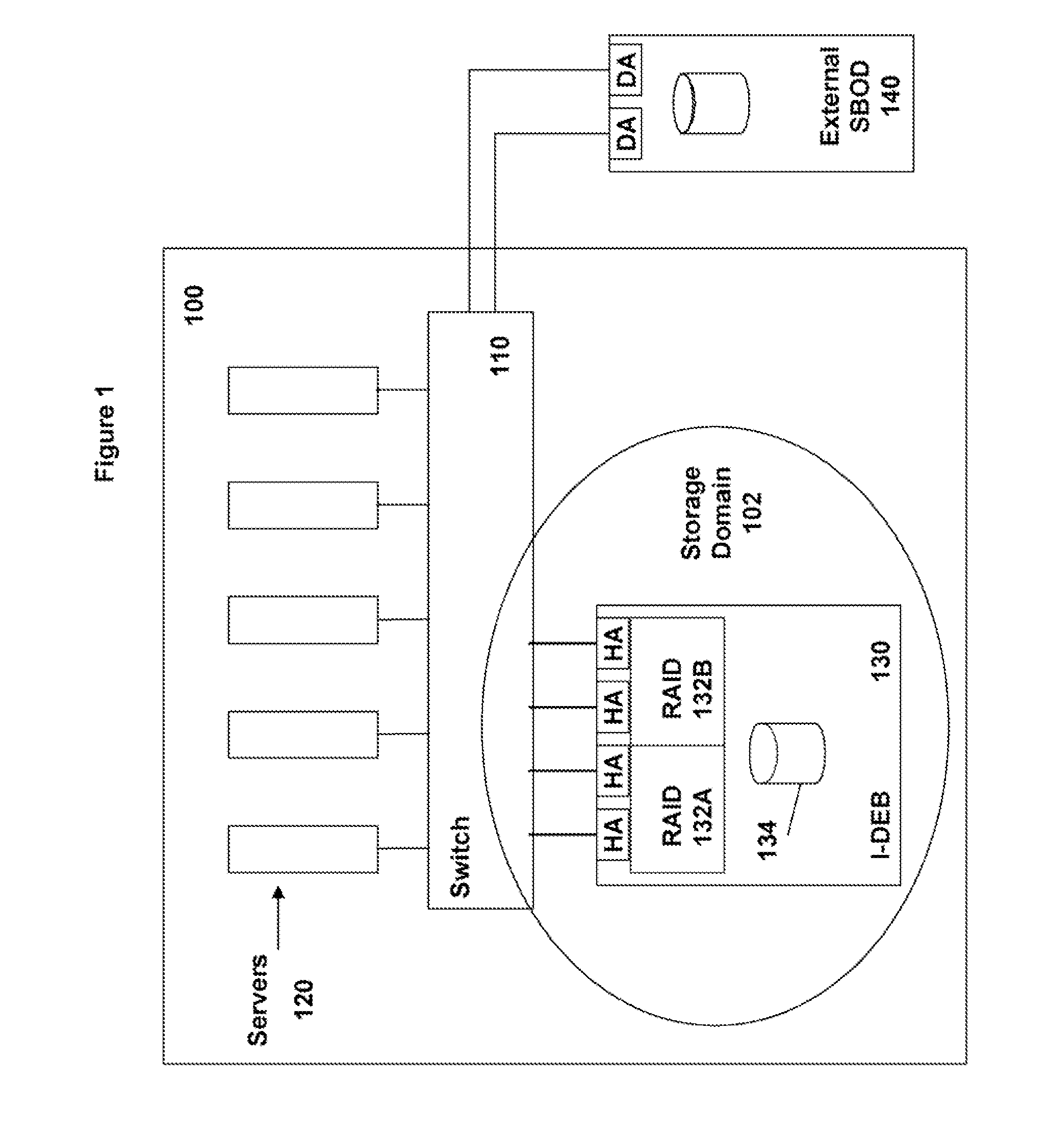
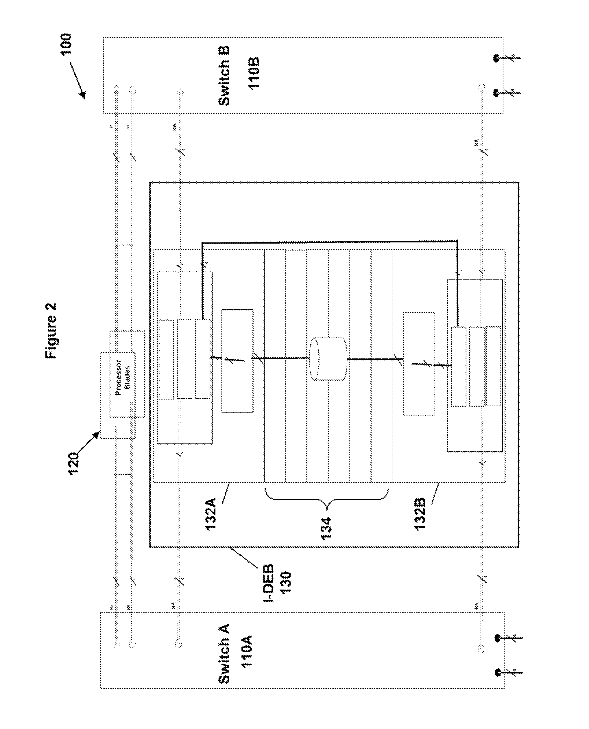
[0017]FIG. 1 is a generalized block diagram of a current version of a blade enclosure 100, such as an IBM BladeCenter. The blade enclosure 100 includes a redundant pair of multi-port switches, represented in FIG. 1 by a single block 110, to which various blades connect. Coupled to the switches 110 through host adapter (HA) ports are one or more processor or server blades 120. Also coupled to the switches 110 through HA ports are one or more integrated drive enclosure blades (I-DEBs) 130, each including a redundant pair of RAID adapters 132A, 1328 and a number of multi-drive trays (MDTs) 134. In one configuration, the I-DEB 130 can have up to six MDTs 134 with three hard disk drives each. The one or more I-DEBs comprise a storage domain or zone 102. Each RAID controller 132A, 132B is coupled to each of the two redundant switches 110 through an HA port; thus data may be exchanged with the servers 120 though a total of four channels, providing high availability and high performance. Th...


PUM


Abstract

A blade enclosure is provided which may accommodate a first configuration which includes integrated drive enclosure blades (I-DEBs) or a second configuration which includes I-DEBs and non-integrated or switched DEBs (S-DEBs). Each I-DEB includes a pair of redundant RAID controllers, each having two configurable ports. In the first configuration, all four ports are configured as host adapter (HA) ports through which data is exchanged with server blades. In the second configuration, one port of each RAID controller is configured as an HA port, through which data is exchanged with server blades, and the other port of each RAID controller is configured as a device adapter (DA) port, through which data may be exchanged with the S-DEB. Zones may also be established to separate traffic between the servers and the I-DEB from traffic between the I-DES and the S-DEB.

Description

TECHNICAL FIELD[0001]The present invention relates generally to blade technology in which enclosures are densely populated with one or more types of computing components and, in particular, to a blade enclosure which is easily configurable and re-configurable to accommodate different types of storage blades.BACKGROUND ART[0002]“Blade” computing systems have become popular recently due in part to the ability to house various primary components in slots in a relatively small enclosure. In addition, blade systems have the advantage of allowing customers to quickly and easily remove and install components to customize the system as the customer's needs change. The components install in slots in the enclosure and connect through a back-plane or mid-plane (hereinafter “connector plane”); thus, customization may be performed without removing, connecting or moving cables.[0003]Through the use of switches, a “universal fabric” may be created in which, for the most part, a component in any sl...

Claims


Application Information

Patent Timeline
Patent Type & Authority Applications(United States)
IPC IPC(8): G06F15/177
CPCG06F3/0605G06F3/0607G06F3/0635G06F3/0637G06F11/2089G06F3/0674G06F3/0689G06F11/201G06F3/0658
Inventor ISLAM, SHAH MOHAMMAD REZAULLUCAS, GREGG STEVEN
Owner IBM CORP
Features
  • R&D
  • Intellectual Property
  • Life Sciences
  • Materials
  • Tech Scout
  • Unparalleled Data Quality
  • Higher Quality Content
  • 60% Fewer Hallucinations
Learn More