RAID memory system

a memory controller and raid technology, applied in the field of raid memory controllers, can solve the problems of increasing the number of pins and significantly driving up the component cost of the raid memory controller, and the reliability of the stripe set is less than the reliability of its least reliable member,

Inactive Publication Date: 2006-08-29
HEWLETT PACKARD DEV CO LP
View PDF20 Cites 199 Cited by
  • Summary
  • Abstract
  • Description
  • Claims
  • Application Information

AI Technical Summary

Problems solved by technology

The reliability of the stripe set is less than the reliability of its least reliable member.
This is an expensive approach and is not popularly used.
Due to fabrication costs, and as is known, this increased pin count can significantly drive up the component cost of the RAID memory controller 10.
This, unfortunately, requires an additional level of hierarchy and additional chips and system complexity.

Method used


Image

  • RAID memory system
  • RAID memory system
  • RAID memory system

Examples


Embodiment Construction

[0020]As described herein, there are various aspects and embodiments of the present invention. In accordance with one embodiment, the present invention is directed to a unique RAID memory system.

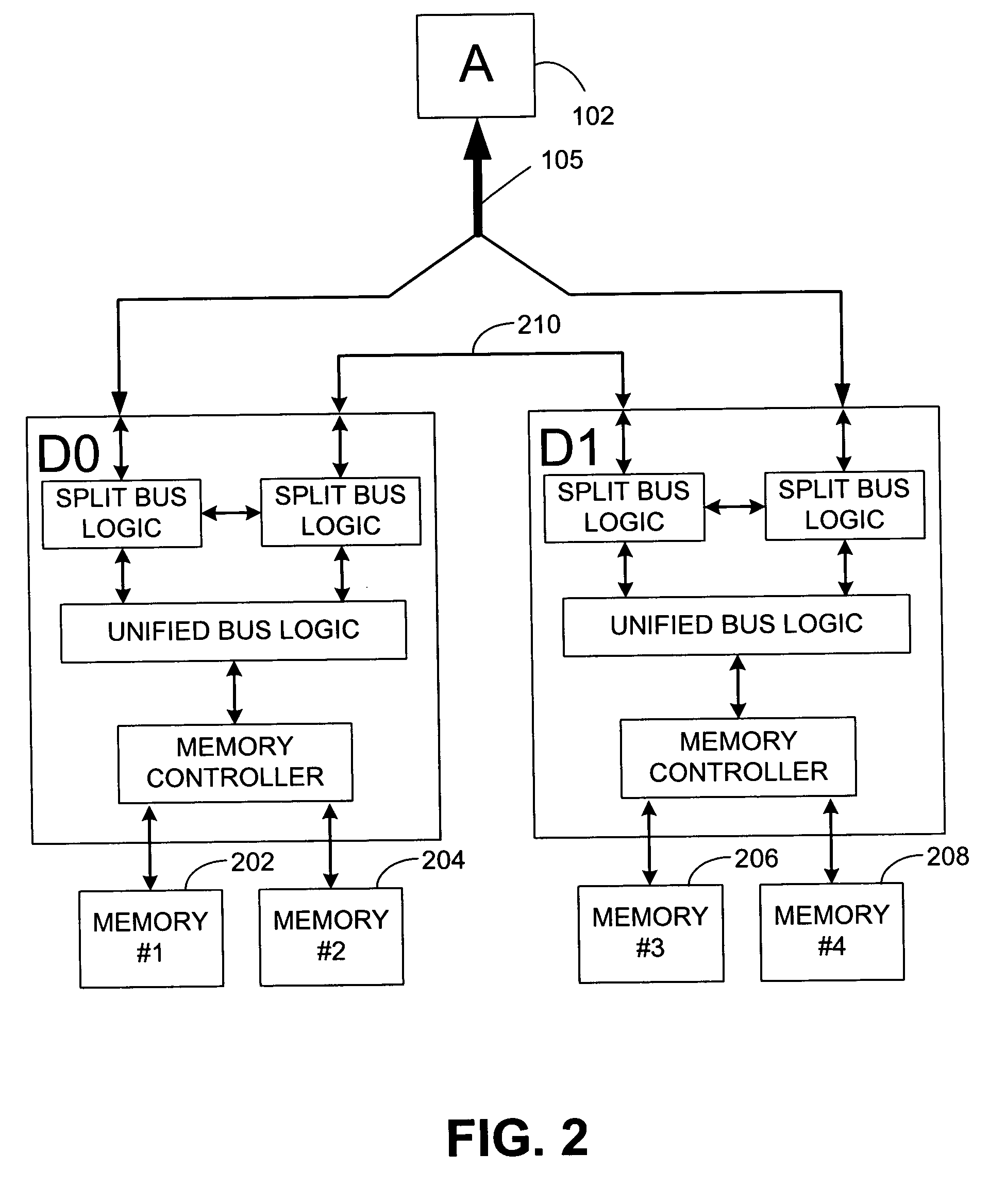
[0021]Reference is now made to FIG. 2, which illustrates an embodiment of a system having cooperative memory controllers D0 and D1 that control data access to memories 202, 204, 206 and 208. One unique aspect of the system illustrated in FIG. 2 relates to the division of the system bus 105. In this regard, each memory controller D0 and D1 is directly coupled to only a portion of the system bus 105. A separate, inter-chip bus 210 provides for direct communication between controllers D0 and D1. Information communicated from the system bus 105 to chip D0 may be communicated, as needed, to chip D1 over this inter-chip bus 210. The embodiment of the system illustrated in FIG. 2, including the manner in which information is communicated among the various components illustrated therein, is fully de...


PUM


Abstract

Embodiments of the present invention are broadly directed to a memory system. In one embodiment, a first data memory is coupled to a first memory controller and a second data memory is coupled to a second memory controller. A parity memory is coupled to a parity controller, the parity controller being directly coupled to both the first memory controller and the second memory controller. Parity data control logic is configured to store and retrieve parity information associated with data stored in both the first data memory and the second data memory, the parity data control logic configured to interleave within the parity memory parity data associated with data stored in the first data memory with parity data associated with data stored in the second data memory.

Description

BACKGROUND[0001]As is known, redundant array of inexpensive disks (RAID) is a technology used to improve the input / output performance and reliability of mass storage devices. A RAID array incorporates fault tolerance by using a redundant architecture, and the disk controller which controls a RAID array is called a RAID controller. In RAID systems, data is stored across multiple storage units (e.g., disks) in order to provide immediate access to the data despite the failure of one or more storage units.[0002]Fundamental to RAID technology is “striping,” which refers to a particular method of combining multiple storage units into one logical storage unit. Striping partitions the storage space of each drive into “stripes” that can be as small as one sector (512 bytes) or as large as megabytes. These stripes are then interleaved in a rotating sequence, so that the combined space is composed alternatively of stripes from each drive.[0003]One major task of a RAID controller is to protect ...

Claims


Application Information

Patent Timeline
Patent Type & Authority Patents(United States)
IPC IPC(8): G06F12/00G06F12/16G06F3/06
CPCG06F11/1076
Inventor THAYER, LARRYRENTSCHLER, ERIC MCCUTCHEONTAYLER, MICHAEL KENNARD
Owner HEWLETT PACKARD DEV CO LP
Why Eureka
Try Eureka