Movable Sinker Apparatus And Sinker Of Weft Knitting Macine

Inactive Publication Date: 2008-02-14
SHIMA SEIKI MFG LTD
View PDF12 Cites 3 Cited by
  • Summary
  • Abstract
  • Description
  • Claims
  • Application Information

AI Technical Summary

Benefits of technology

[0018]Furthermore, an embodiment of the invention is directed to a sinker for use in a movable sinker apparatus having a base portion which is supported in a swingingly displaceable manner in a vicinity of a needle bed gap on a needle bed and a front end portion which is moved forward to the needle bed gap to knit a knitting fabric by an interaction with a knitting needle, the sinker comprising:

Problems solved by technology

However, a knitting fabric is not sufficiently pulled down depending on knitting conditions, and thus there is a request for a more reliable pulling-down function.

Method used


Image

  • Movable Sinker Apparatus And Sinker Of Weft Knitting Macine
  • Movable Sinker Apparatus And Sinker Of Weft Knitting Macine
  • Movable Sinker Apparatus And Sinker Of Weft Knitting Macine

Examples


Embodiment Construction

[0032]Now referring to the drawings, example embodiments of the invention are described below.

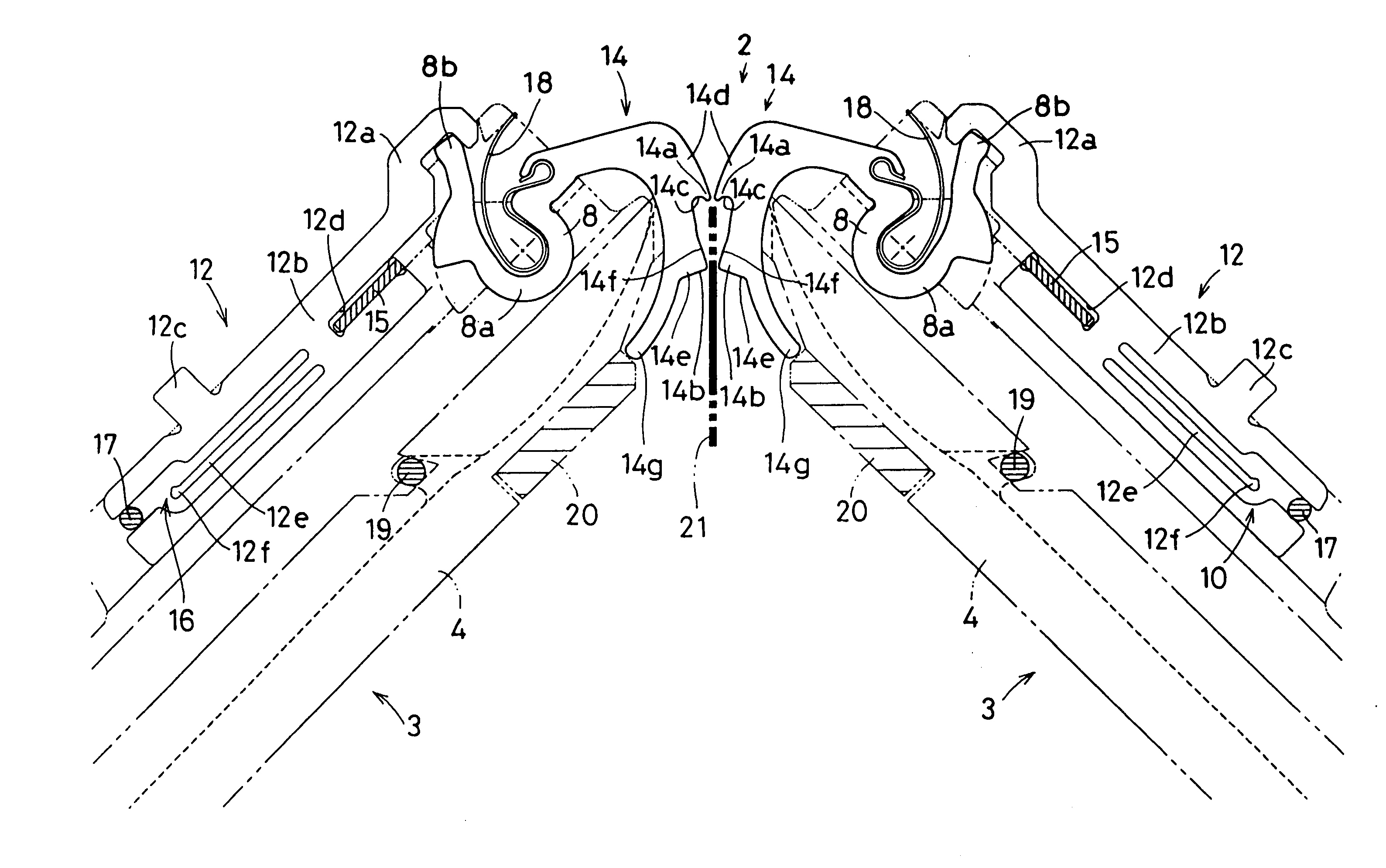
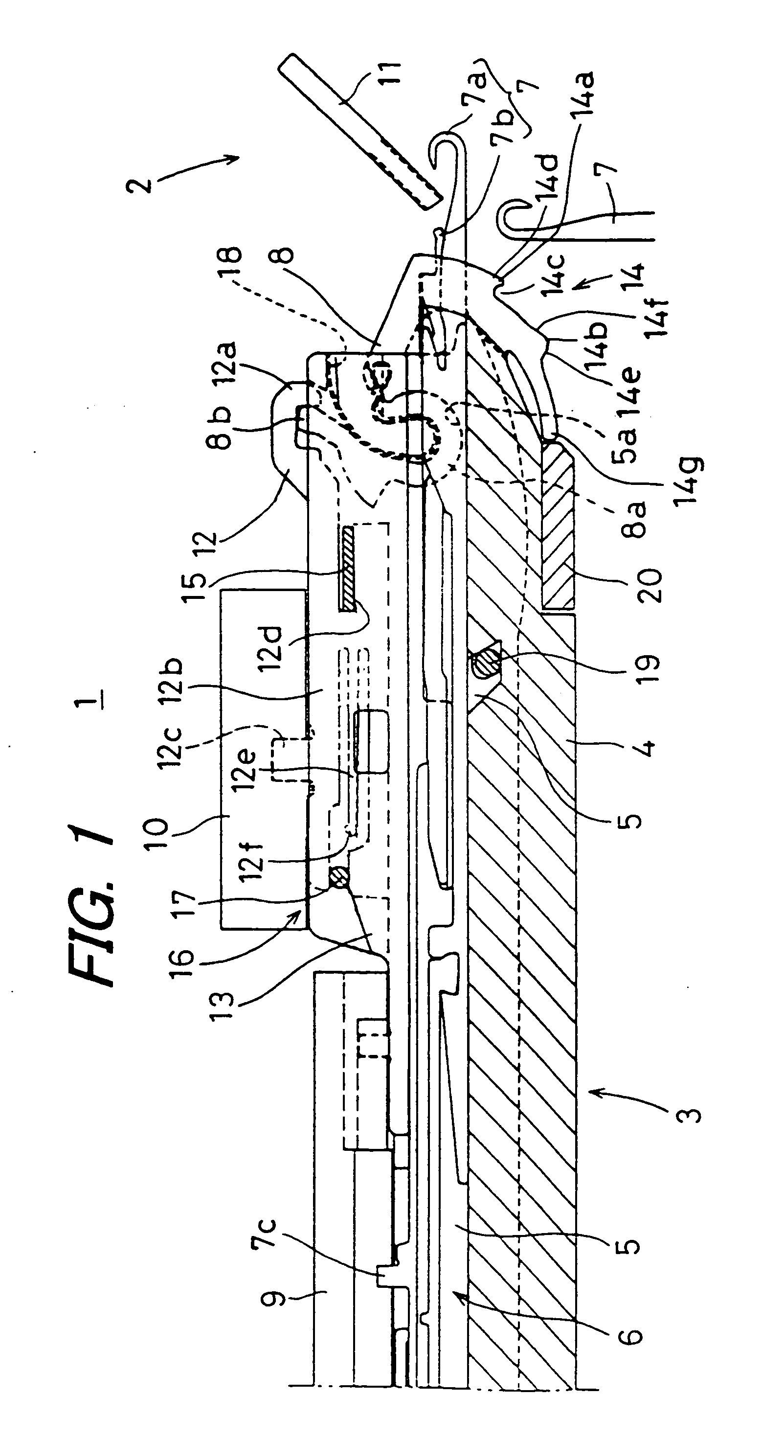
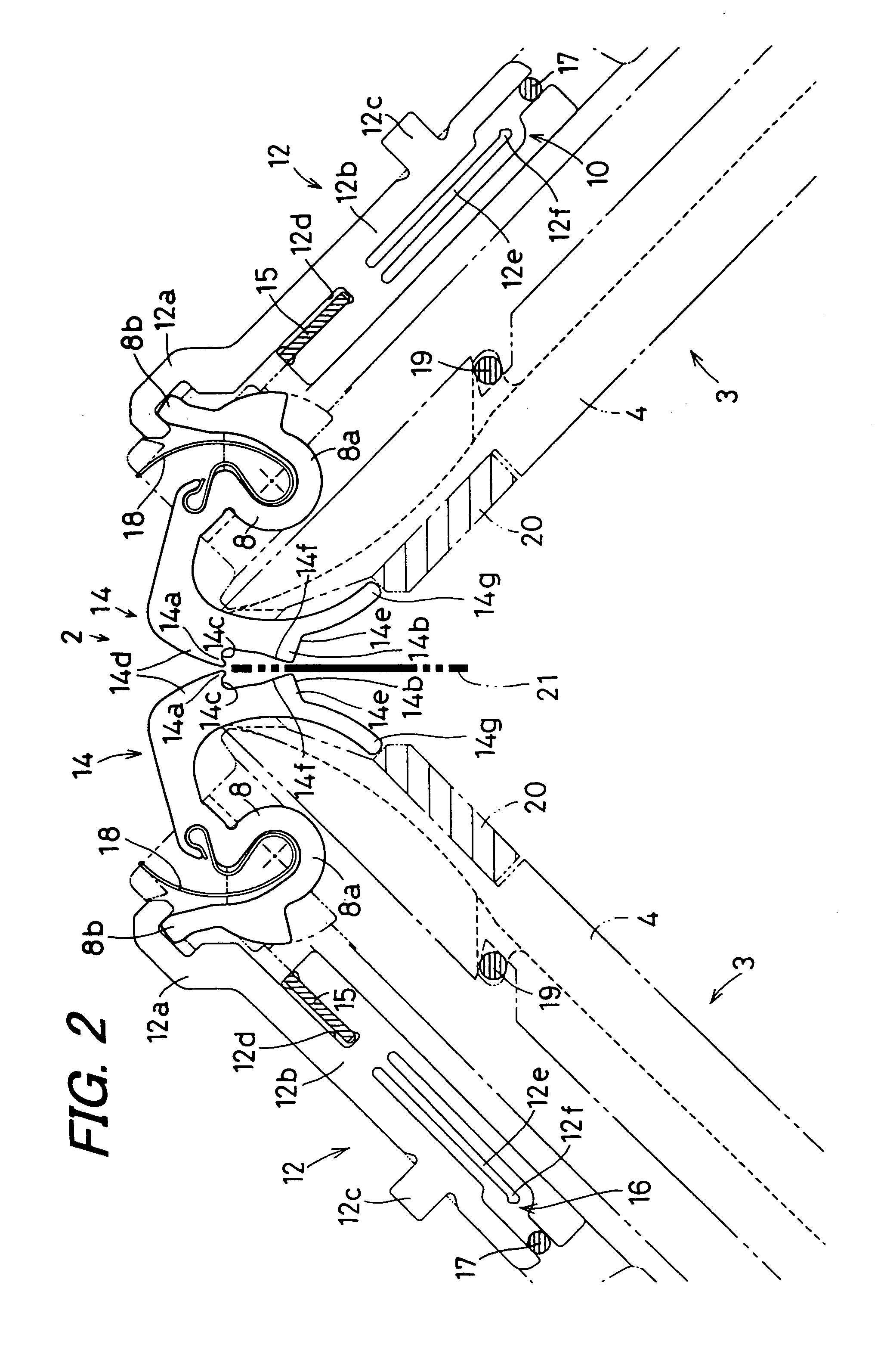
[0033]FIG. 1 shows the configuration of the main portions of a movable sinker apparatus 1 of a weft knitting machine according to an embodiment of the invention. The movable sinker apparatus 1 of a weft knitting machine is provided in a weft knitting machine in which front and rear needle beds are opposed to each other at a needle bed gap 2. In the drawing, one needle bed 3 is shown and the other needle bed is not shown. The needle bed 3 is inclined with respect to the needle bed gap 2 such that the needle bed 3 is high on the needle bed gap side and becomes lower as being away from the needle bed gap. In other words, the front and rear needle beds 3 are arranged in the shape of V upside down that is centered on the needle bed gap 2. However, for the sake of convenience, one needle bed 3 is shown in a horizontal state. The configuration of one needle bed 3 is basically similar to the config...


PUM


Abstract

There are provided a movable sinker apparatus of a weft knitting machine and a sinker which are capable of holding and pressing down a knitting yarn of a previous loop and sufficiently pulling down a knitting fabric. At forward positions of the sinkers, second protruding portions are close to each other, and thus a knitting fabric can be sandwiched therebetween. When the front and rear needle beds are faced each other so as to be symmetric at the needle bed gap, the forces of the wire springs are applied so as to pull down the knitting fabric in the vertical direction. A knitting yarn receiving portion is formed on a first protruding portion of the front end portion on the sinker, and thus it is possible to retain a knitting yarn of a previous loop and prevent the knitting yarn from moving as the knitting needle moves forward. the second protruding portion that projects outward in a radial direction is formed on a portion close to a front end of the first protruding portion, and the knitting fabric can be sandwiched and pulled down by the second protruding portions provided on the needle beds that are opposed to each other.

Description

PRIORITY STATEMENT[0001]This application is the national phase under 35 U.S.C. § 371 of PCT International Application No. PCT / JP2005 / 005962 which has an International filing date of Mar. 29, 2005, which designated the United States of America and which claims priority on Japanese Patent Application number P2004-103185 filed Mar. 31, 2004, the entire contents of which are hereby incorporated herein by reference.TECHNICAL FIELD [0002]The present invention generally relates to a movable sinker apparatus and / or a sinker, of a weft knitting machine. For example, it may relate to one that can press a knitting fabric and pull down the knitting fabric to a lower portion of a needle bed at an appropriate timing during knitting.BACKGROUND ART [0003]A movable sinker apparatus has been conventionally used that includes, between knitting needles arranged on a needle bed in a weft knitting machine, a sinker displaced by a cam mechanism provided on a carriage such that the sinker is swingingly di...

Claims


Application Information

Patent Timeline
IPC IPC(8): D04B15/06D04B15/90
CPCD04B15/362D04B15/06D04B15/90D04B15/70
Inventor MIYAMOTO, MASAKI
Owner SHIMA SEIKI MFG LTD
Why Eureka
Try Eureka