Plate replacing apparatus

a plate and plate technology, applied in the direction of addressographs, printing presses, printing presses, etc., can solve the problems of insufficient stiffness, roller interference with plate vice,

Inactive Publication Date: 2008-02-14
MITSUBISHI HEAVY IND LTD
View PDF11 Cites 34 Cited by
  • Summary
  • Abstract
  • Description
  • Claims
  • Application Information

AI Technical Summary

Benefits of technology

[0006]It is an object of the present invention to at least partially solve the problems in the conventional technology.

Problems solved by technology

Therefore, the roller interferes with a vice of the plate.
In a case in which the vice is notched, however, the stiffness may drop insufficiently.

Method used


Image

  • Plate replacing apparatus
  • Plate replacing apparatus
  • Plate replacing apparatus

Examples


Embodiment Construction

[0020]Embodiments of the present invention are explained in detail below with reference to the accompanying drawings. The present invention is not limited to the embodiments. Incidentally, components capable of being easily conceived by those skilled in the art are to be employed in the embodiments.

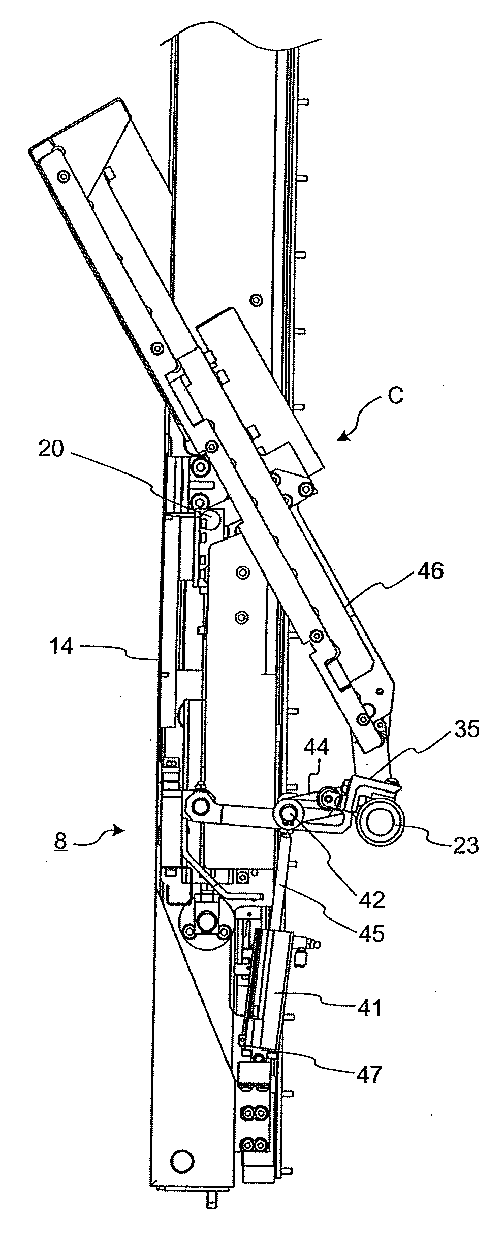
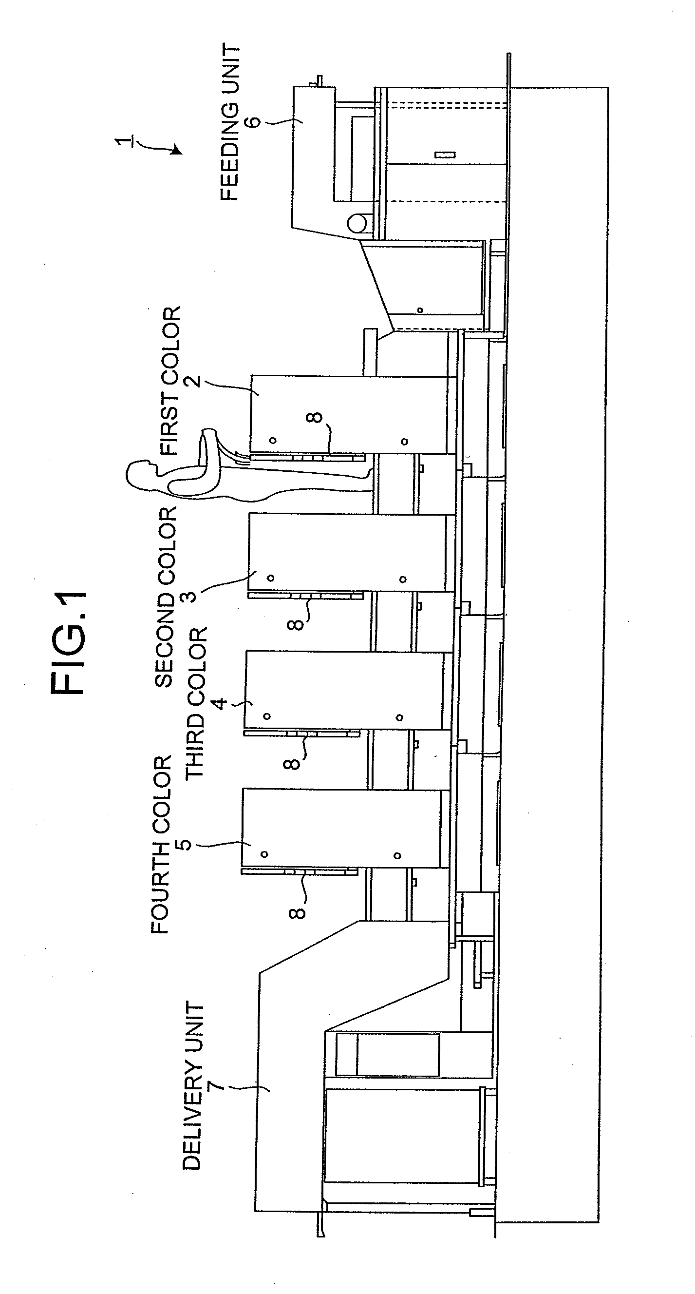
[0021]FIG. 1 is a side view of a printing press 1 according to an embodiment of the present invention, including a plate replacing apparatus. The printing press 1 includes a feeding unit 6, printing units 2, 3, 4, and 5, and a delivery unit 7. The feeding unit 6 feeds paper to be printed thereon to the printing unit. The printing units 2, 3, 4, and 5 respectively print an image in different colors, such as in cyan, magenta, yellow, and black, on the paper fed from the feeding unit 6 by overlapping each color sequentially. The printed paper is output by the delivery unit 7. Each of the printing units 2, 3, 4, and 5 respectively includes a number of rollers, such as a plate cylinder and an ...


PUM


Abstract

A plate replacing apparatus includes a plate-winding support roller that presses a plate on a plate cylinder and a plate pressing unit that rotates around the plate-winding support roller and thereby pressing a trailing end of the plate in an edge portion of the plate pressing unit. The plate pressing unit presses the plate in a position in front of a lower tooth of a vice built in the plate cylinder.

Description

BACKGROUND OF THE INVENTION[0001]1. Field of the Invention[0002]The present invention relates to a plate replacing apparatus included in a printing press, and more particularly, to a plate replacing apparatus that winds a plate around a plate cylinder.[0003]2. Description of the Related Art[0004]In a conventional plate replacing apparatus included in a printing press as disclosed in Japanese Patent No. 2956021, a new plate is pressed by a roller and wound around a plate cylinder.[0005]To ensure the stiffness required for pressing the plate, the roller needs to have a diameter at least a predetermined length. Therefore, the roller interferes with a vice of the plate. In other words, the roller cannot firmly press a trailing end of the plate around the vice. As a result, the plate is not wound around the plate cylinder precisely. To solve the problem, a portion to be pressed by the roller is extended, or the vice is notched so that the roller can firmly press the plate to its trailing...

Claims


Application Information

Patent Timeline
Patent Type & Authority Applications(United States)
IPC IPC(8): B41F27/12
CPCB41P2227/62B41F27/1206
Inventor YOKOYAMA, MINORUYANO, HIROYUKI
Owner MITSUBISHI HEAVY IND LTD
Why Eureka
Try Eureka