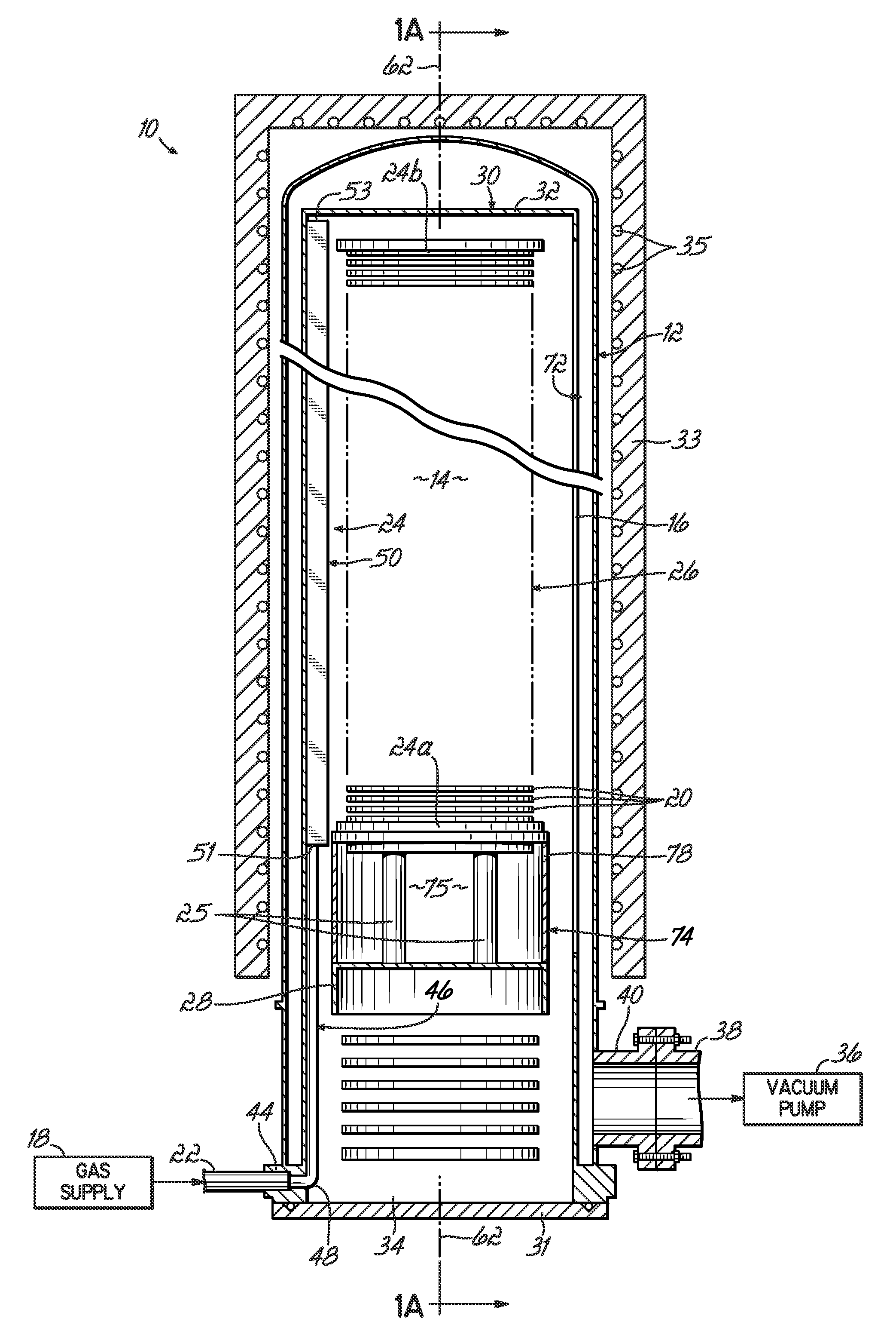
Thermal processing system with improved process gas flow and method for injecting a process gas into a thermal processing system
a technology of thermal processing system and process gas, which is applied in the direction of coating, chemical vapor deposition coating, metallic material coating process, etc., can solve the problems of thermal processing system may form layers on the substrate, and conventional measures may also be ineffective in preventing thickness and composition non-uniformities among different lots of processed substrates
- Summary
- Abstract
- Description
- Claims
- Application Information
AI Technical Summary
Problems solved by technology
Method used
Image
Examples
example 2
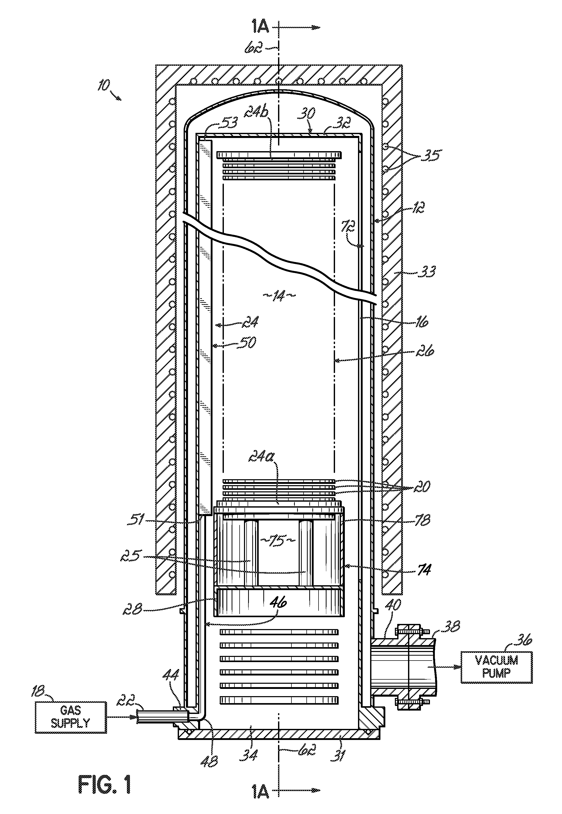
[0070]A CFD computation was performed under conditions identical to those of Example 1 and using a gas injector similar to the gas injector depicted in FIGS. 1-4. FIG. 11 is a graph representing the CFD computation of mass flow distribution as a function of injection opening number for the three different nitrogen gas flows. FIG. 12 is a graph representing the computed mass flux as a function of location in the process chamber for the three different nitrogen gas flows. The top ⅓rd of the process chamber is located near the closed end of the liner most remote from the pumping port and the bottom ⅓rd of the process chamber is located adjacent to pumping port.
[0071]The gas injection outlets or openings were distributed along the length of the gas injector and an average of 0.578% of the total gas flow was directed through each individual opening. At a nitrogen gas flow of 333 sccm, the computed mass flow distribution from the gas injection outlets exhibited a standard deviation of 3.5...
example 3
[0072]A CFD computation was performed with conditions identical to those of Example 2, other than the introduction into the CFD model of a gas injector similar to the gas injector of FIGS. 5-7 and having an LB / LI ratio of 0.4. FIG. 13 is a graph representing the computed mass flow distribution as a function of injection opening number for the three different nitrogen gas flows. FIG. 14 is a graph representing the computed mass flux as a function of location in the process chamber for the three different nitrogen gas flows.
[0073]The gas injection outlets or openings were distributed along the length of the gas injector and an average of 0.578% of the total gas flow was directed through each opening. At a nitrogen gas flow of 333 sccm, the computed mass flow distribution from the gas injection outlets exhibited a standard deviation of 1.33% and a range of ±2.46%. At a nitrogen gas flow of 1000 sccm, the computed mass flow distribution from the gas injection outlets exhibited a standar...
PUM
| Property | Measurement | Unit |
|---|---|---|
| outer diameters | aaaaa | aaaaa |
| outer diameters | aaaaa | aaaaa |
| length | aaaaa | aaaaa |
Abstract
Description
Claims
Application Information
 - Generate Ideas
- Intellectual Property
- Life Sciences
- Materials
- Tech Scout
- Unparalleled Data Quality
- Higher Quality Content
- 60% Fewer Hallucinations
Browse by: Latest US Patents, China's latest patents, Technical Efficacy Thesaurus, Application Domain, Technology Topic, Popular Technical Reports.
© 2025 PatSnap. All rights reserved.Legal|Privacy policy|Modern Slavery Act Transparency Statement|Sitemap|About US| Contact US: help@patsnap.com


