Mems-based projector suitable for inclusion in portable user devices

Inactive Publication Date: 2008-02-14
MICROVISION
View PDF10 Cites 50 Cited by
  • Summary
  • Abstract
  • Description
  • Claims
  • Application Information

AI Technical Summary

Benefits of technology

[0016] In some embodiments an optical component may be used to provide a number of functions that would otherwise require multiple different components (e.g., mirrors, prisms, polarizers, etc.). The optical component may, for example, reflect a light beam towards a MEMS scanner and receive the light beam from the MEMS scanner to externally project the light beam on a screen. The optical component may provide optical and chromatic aberration correction which would otherwise require a number of other mechanical components which increase the size of the MEMS-based projector. Additionally, the optical component may include a wedge that may be used to steer the externally projected beam along the vertical or horizontal direction. The optical component m

Problems solved by technology

Integrating such MEMS scanners into portable user devices such as small form factor devices however may sometimes prove to be difficult.
The difficulties typically arise from the size constraints, power restrictions, component sizes, heat limitations, etc.
For example, in the case of a cell phone, the antenna may be positioned in the corner of the phone and limit the space available for placin

Method used


Image

  • Mems-based projector suitable for inclusion in portable user devices
  • Mems-based projector suitable for inclusion in portable user devices
  • Mems-based projector suitable for inclusion in portable user devices

Examples


Embodiment Construction

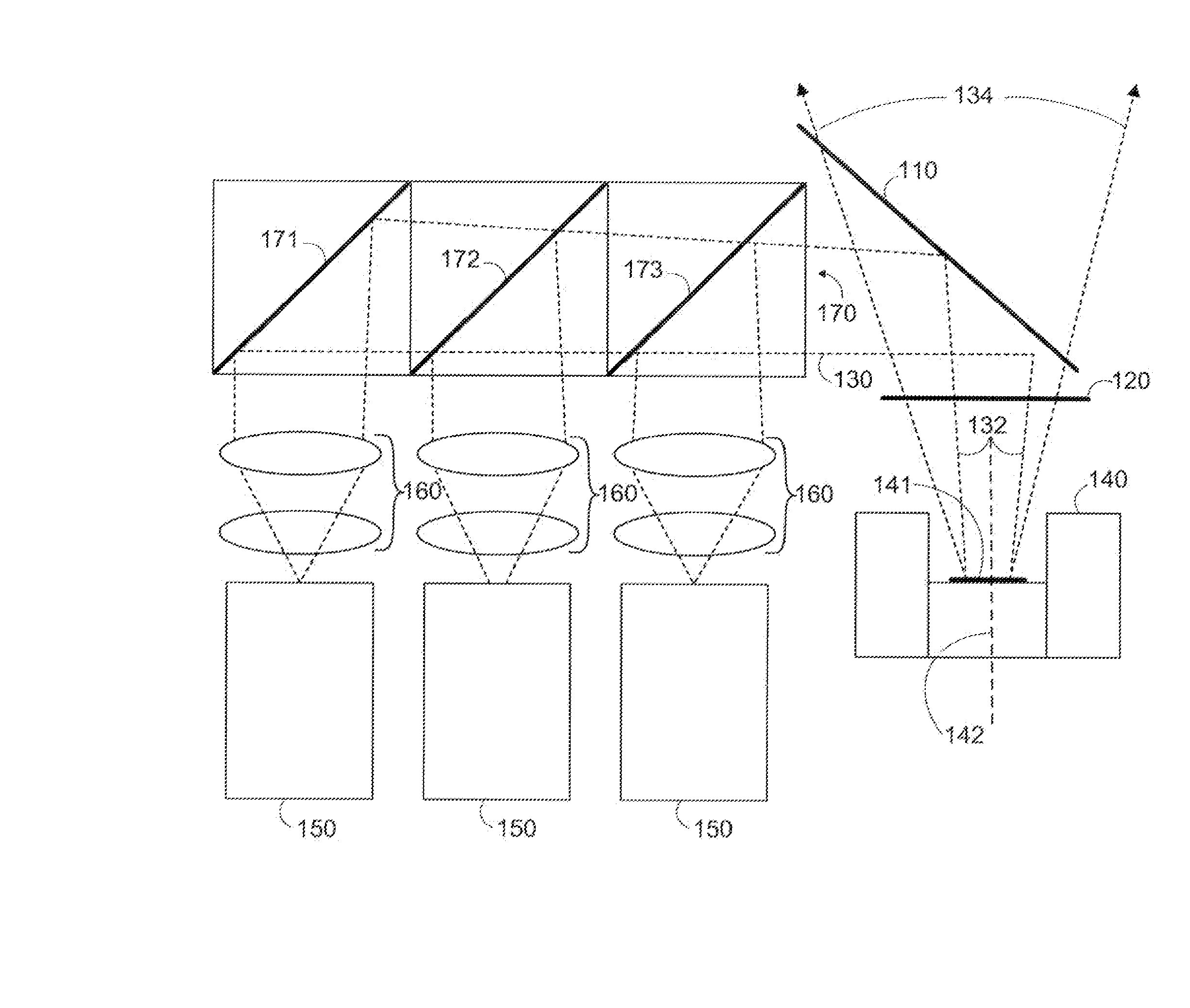
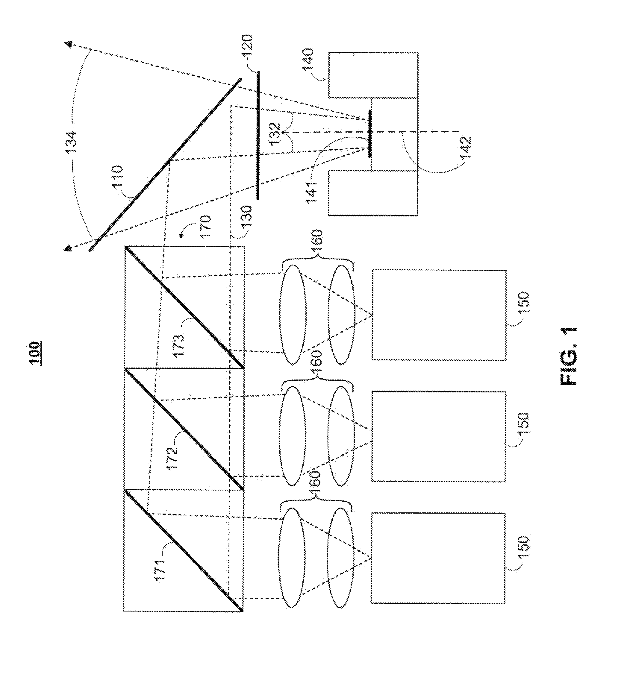
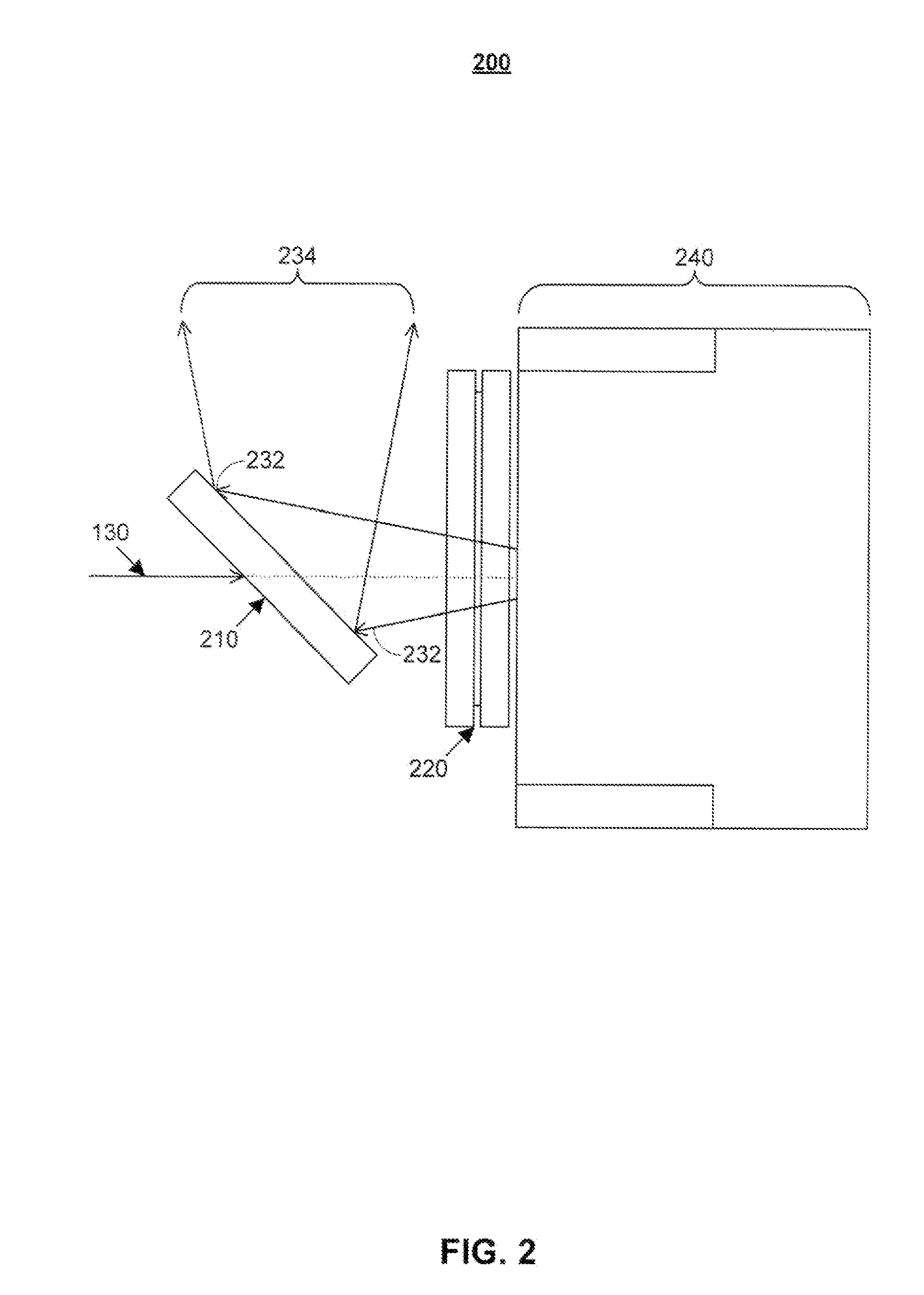
[0041] In accordance with some embodiments of the invention a light beam may be received by a MEMS-based projector. The projector may scan and externally project the beam in a direction substantially perpendicular to the direction of the received light beam. The received beam may either be s-polarized (FIG. 1) or p-polarized (FIG. 2). Depending on its polarization, the received beam may either be received in a direction substantially parallel or perpendicular to the normal of the mirror of the MEMS scanner.

[0042] It should be understood that a static mirror may be added to change directions of the input or projected beams. However, the addition of components in small form factor devices may conflict with various other components included in the devices (e.g., antennas, screens, etc.). Small form factor devices may include cell phones, PDAs, laptops, MP3 players, e-mail devices, or any other portable user equipment devices. The dimensions of small form factor devices such as an MP3 ...


PUM


Abstract

A MEMS-based projector may be included in various user devices. A selective fold mirror, a MEMS-based projector, and a polarization rotator may be oriented to reflect a beam within the device for external projection. Alternatively, a total internal reflection prism may take the place of a selective fold mirror or a polarization rotator and may reduce the number of necessary components in the user device. Various optical components may be placed in the MEMS-based projector and arranged in different positions to reflect a light beam in a desired direction for external projection. The components that make up the MEMS-based projector may depend on the available footprint in the device and the direction in which the light beam is to be projected. Some optical components may provide multiple functionalities which would otherwise require multiple components and may reduce the size of the projector.

Description

[0001] This application is a non-provisional of U.S. provisional patent Application No. 60 / 811,655, filed Jun. 6, 2006 and a continuation-in-part of U.S. patent application Ser. No. 11 / 786,423, filed Apr. 10, 2007 which is a non-provisional of U.S. provisional patent Application No. 60 / 791,074, filed Apr. 11, 2006, each of which is hereby incorporated by reference herein in its entirety.BACKGROUND OF THE INVENTION [0002] Projecting an image from a user equipment device onto an external screen may typically be performed by reflecting a light beam at a particular frequency in the X and Y directions. The light beam may be emitted using a number of lasers or diodes and may be scanned / modulated by a scanning mirror for external projection. For example, in the case of 1D scanners, the scanner may include a first beam director driven to scan the output beam along a single axis and a second beam director driven to scan the output beam in a second axis. In such a system, both scanners are re...

Claims


Application Information

Patent Timeline
IPC IPC(8): G02B26/10
CPCG02B27/104G02B27/1066G02B27/141G02B27/145H04N9/3197G02B27/283H04N9/3111H04N9/3129H04N9/3173G02B27/28
Inventor MILLER, JOSHUA O.JAMES, RICHARD A.DEJONG, CHRISTIAN DEANSPROWL, ROBERT A.NIESTEN, MAARTEN
Owner MICROVISION
Why Eureka
Try Eureka