Non-aqueous electrolyte secondary cell

a secondary battery and electrolyte technology, applied in the direction of cell components, sustainable manufacturing/processing, final product manufacturing, etc., can solve the problems of prone to malfunction, current interrupting mechanism, etc., and achieve the effect of efficient series connection

Active Publication Date: 2008-02-14
SANYO ELECTRIC CO LTD
View PDF9 Cites 81 Cited by
  • Summary
  • Abstract
  • Description
  • Claims
  • Application Information

AI Technical Summary

Benefits of technology

[0049] Batteries with prismatic outer cans can be efficiently connected in series.

Problems solved by technology

These examples of current interrupting mechanism, however, are susceptible to malfunction due to vibration or impact.

Method used


Image

  • Non-aqueous electrolyte secondary cell
  • Non-aqueous electrolyte secondary cell
  • Non-aqueous electrolyte secondary cell

Examples


first embodiment

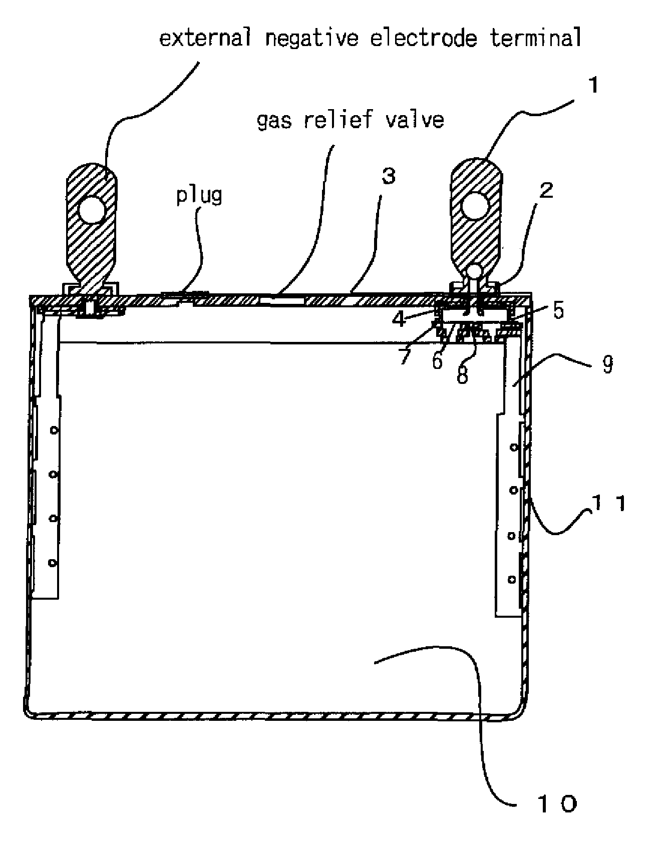
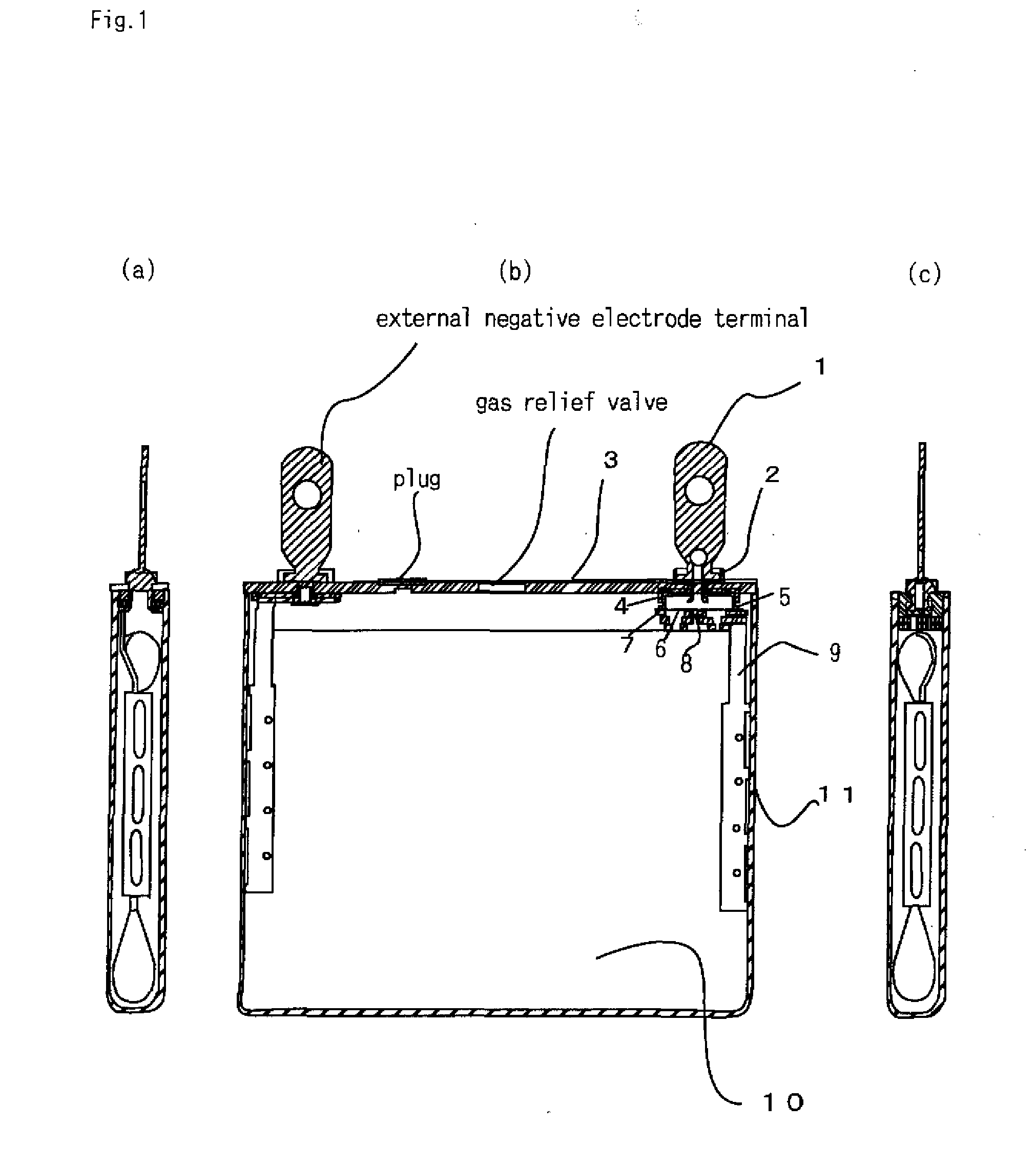
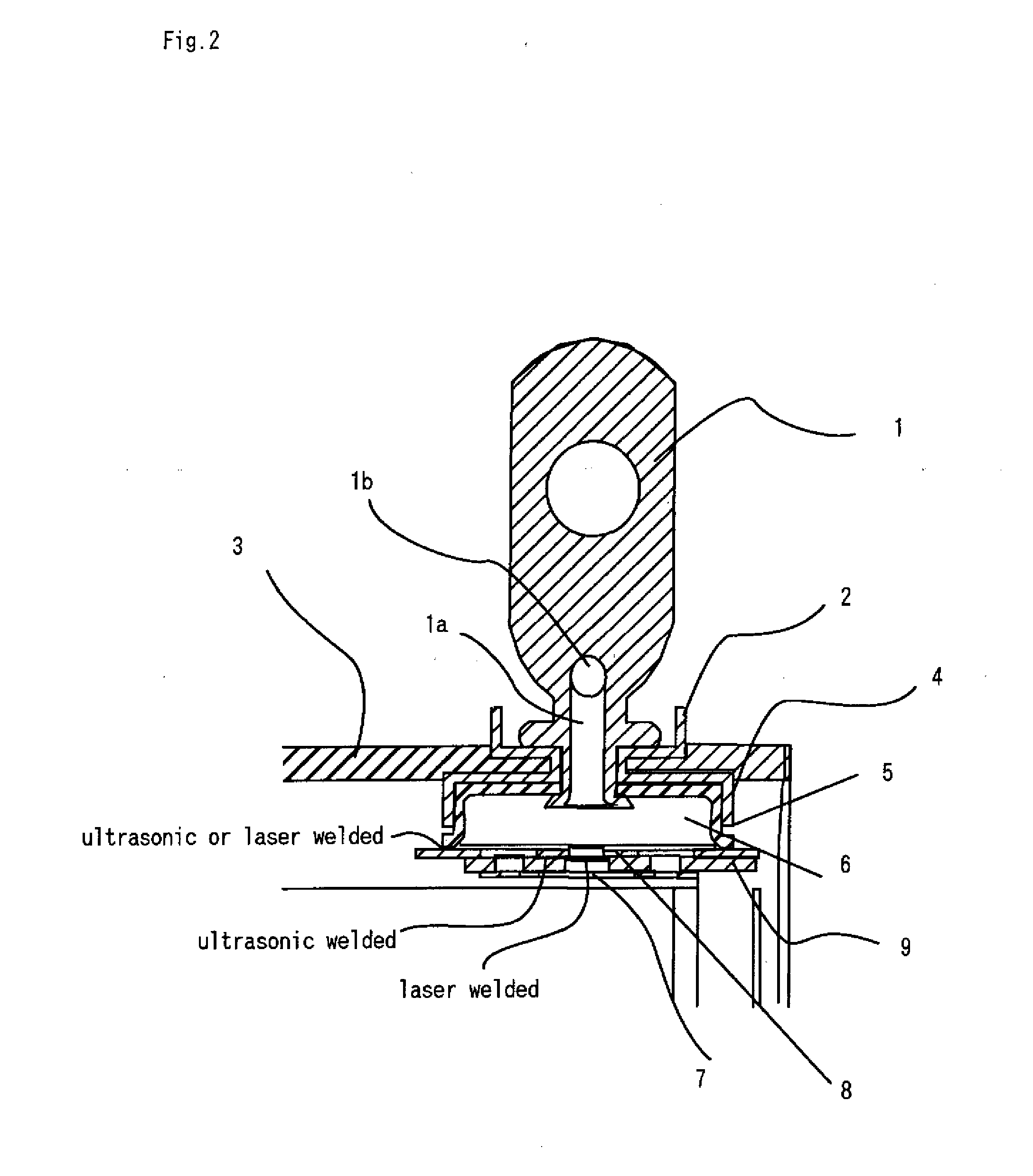
[0076]FIGS. 1A-1C are sectional views of a battery according to a first embodiment; FIG. 2 is an enlarged sectional view of an essential part of the battery; FIG. 3 is an exploded perspective view of the battery; FIGS. 4A and 4B show the operation of the diaphragm of the battery; FIGS. 5A-5C show a current collecting tab holder of the battery; and FIG. 6 is another enlarged sectional view of the essential part of the battery.

[0077] As shown in FIGS. 1A-1C, the battery of the first embodiment includes an outer can 11 and a coiled electrode assembly 10 housed in the outer can 11 laterally to the can axis. The electrode assembly 10 comprises positive and negative electrodes coiled together. The outer can 11 is sealed with a sealing plate 3 having a gas relief valve. The sealing plate 3 has an external positive electrode terminal 1 and an external negative electrode terminal projecting outside the battery therefrom.

[0078] As shown in FIG. 3, the electrode assembly 10 has positive-elec...

second embodiment

[0100] Another structure of the battery of the present invention is shown in FIGS. 7 and 8.

[0101]FIG. 7 is a front view of the entire battery according to the second embodiment, and FIG. 8 is an enlarged right side view of an essential part of the battery shown in FIG. 7.

[0102] As shown in FIG. 7, in the battery of the second embodiment, the sealing plate 3 from which the external electrode terminal 1 projects is provided with a projection 12 projecting toward the outside of the battery. The projection 12 accommodates one end (the bottom side) of the external electrode terminal 1 in its inner space and allows the other end or the top side of the external electrode terminal 1 to project to the outside of the battery. The bottom-side end of the external electrode terminal 1 is swaged as shown in FIG. 8 so as to fix the external electrode terminal 1 to the sealing plate 3.

[0103] In FIG. 7, the numeral 13 indicates a space used to provide electrical components or gas passages; the nu...


PUM

PropertyMeasurementUnit
frequencyaaaaaaaaaa
accelerationaaaaaaaaaa

Abstract

A non-aqueous electrolyte secondary battery has a current interrupting mechanism with excellent impact and vibration resistance. The mechanism includes a fragile portion which breaks when the diaphragm deforms and rises upward, thereby interrupting current flow thereto; and an insulating current collecting tab holder into which a part of a current collecting tab is inserted. The tab holder has a tab receiving portion into which the insert member of the tab is inserted. The tab receiving portion is provided on the inner and outer surfaces thereof with a holder hole, which overlaps with a throughhole when the insert member is inserted. The diaphragm is disposed outside the tab receiving portion so as to cover the holder hole and electrically connected at its center bottom to the fragile portion via the holder hole. The gas pressure in the battery acts on the fragile portion and the inner side of the diaphragm.

Description

BACKGROUND OF THE INVENTION [0001] 1. Field of the Invention [0002] The present invention relates to non-aqueous electrolyte secondary batteries, and more particularly to non-aqueous electrolyte secondary batteries having a current interrupting mechanism with excellent impact resistance. [0003] 2. Description of the Prior Art [0004] In recent years, non-aqueous electrolyte secondary batteries have been used not only in compact devices such as mobile phones, notebook PCs, and digital cameras but also as the power source for driving electric vehicles and hybrid vehicles. [0005] When used for the latter application, a plurality of batteries are connected in series to produce a high output. Non-aqueous electrolyte secondary batteries are made of highly reactive materials and therefore required to have a higher safety level than when used as the power source in the latter application than when used in compact devices. These secondary batteries are also required to have excellent impact a...

Claims


Application Information

Patent Timeline
Patent Type & Authority Applications(United States)
IPC IPC(8): H01M2/12H01M10/00H01M10/05H01M10/0587H01M50/574
CPCH01M2/34Y02T10/7011H01M10/052H01M2/347Y02E60/10H01M50/579Y02P70/50H01M50/574
Inventor YAMAUCHI, YASUHIRONAKANISHI, NAOYANOHMA, TOSHIYUKI
Owner SANYO ELECTRIC CO LTD
Why Eureka
Try Eureka