Supercharge Your Innovation With Domain-Expert AI Agents!

Electrical connector with air-circulation features

a technology of air circulation and electric connectors, applied in the direction of photomechanical equipment, coupling device connections, instruments, etc., can solve the problems of reducing the reliability and service life of the connector, limiting the amount of power that can be transmitted through the connector, and increasing the overall footprint of the connector

Active Publication Date: 2008-02-14
FCI AMERICAS TECH LLC
View PDF99 Cites 29 Cited by
  • Summary
  • Abstract
  • Description
  • Claims
  • Application Information

AI Technical Summary

Benefits of technology

[0007] To help solve the problem of excessive heating of electrical connectors used to transmit power, the present invention is directed to an electrical connector comprising an electrical conductor for transmitting electrical power, and a housing. The electrical conductor is mounted in the housing so that the housing and the electrical conductor define a channel for circulating airflow through the housing and along a surface of the electrical conductor.

Problems solved by technology

Excessive heating of a connector can limit the amount of power that can be transmitted through the connector.
Moreover, operating a connector at high temperatures can potentially reduce the reliability and service life of the connector.
Moreover, high operating temperatures may require that the connector be spaced from other components by a greater distance than otherwise would be required, i.e., high operating temperatures can increase the overall footprint of a connector.

Method used


Image

  • Electrical connector with air-circulation features
  • Electrical connector with air-circulation features
  • Electrical connector with air-circulation features

Examples


Embodiment Construction

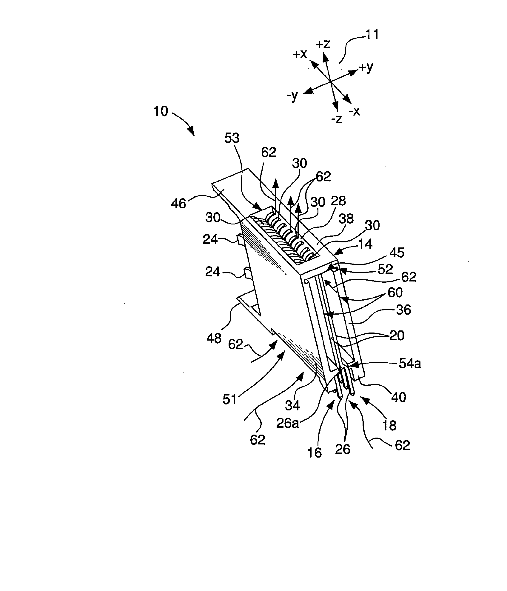
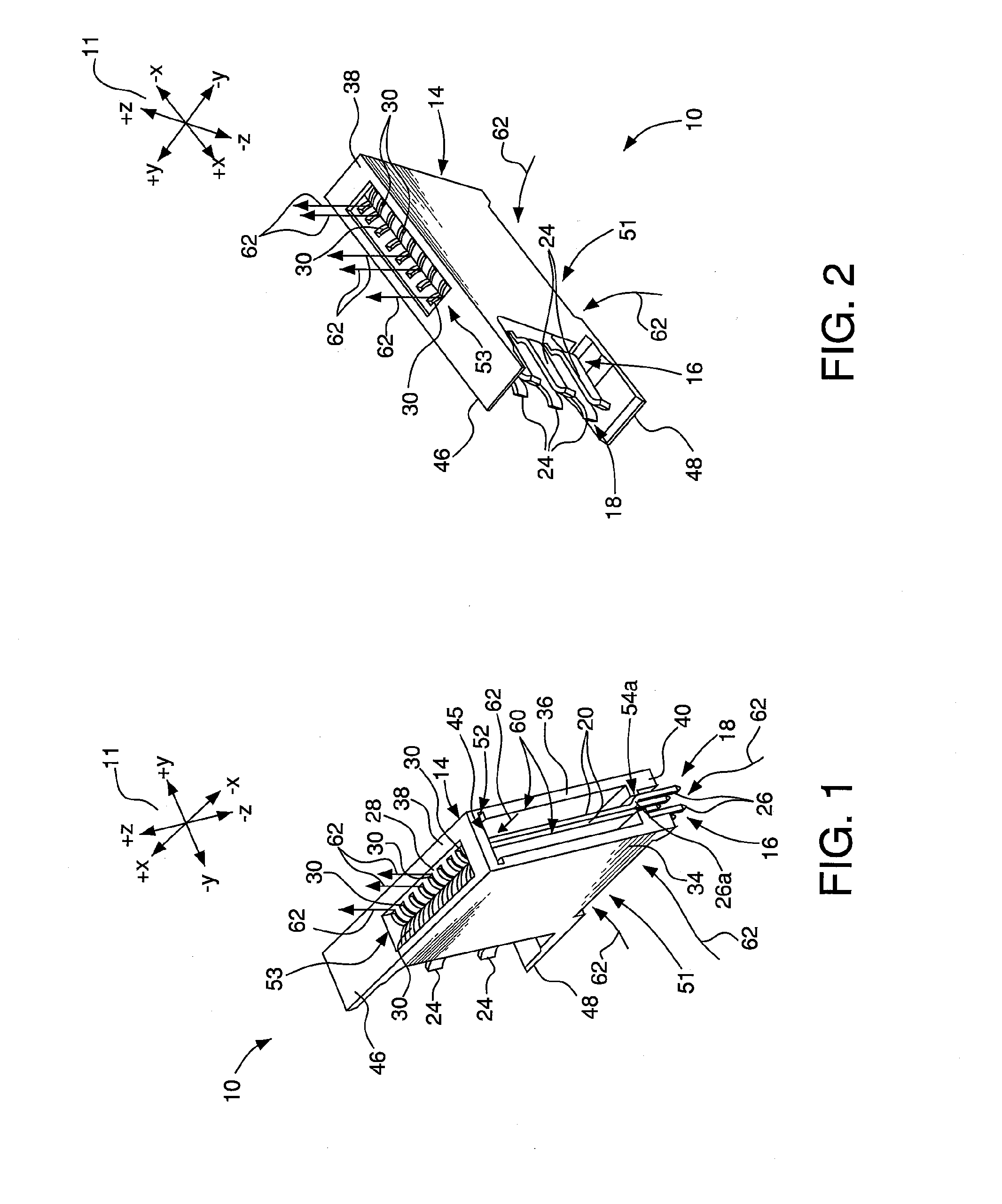
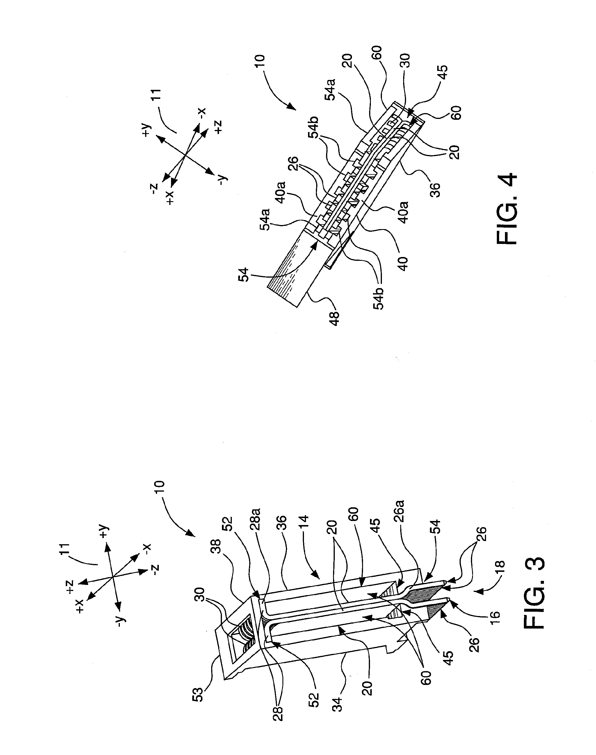
[0020] FIGS. 1 to 5 depict a preferred embodiment of an electrical connector 10. The FIGs. are each referenced to a common coordinate system 11. Directional terms such as “top,” bottom,”“vertical,” horizontal,”“above,”“below,” etc., are used herein with reference to the component orientations depicted in FIG. 5. These terms are used for exemplary purposes only, and are not intended to limit the scope of the appended claims.

[0021] The connector 10 can be mounted on a substrate 12, as depicted in FIG. 5. The connector 10 comprises a housing 14. The connector 10 also comprises a first conductor 16 and a second conductor 18 mounted in the housing 14.

[0022] The first conductor 16 and the second conductor 18 are substantially identical, with the exception that the first and second conductors 16, 18 are configured in a left and right hand configuration. In other words, the first and second conductors 16, 18 are symmetrically disposed about a vertically-oriented plane passing through the ...


PUM


Abstract

A power contact as disclosed herein may include first and second conductive plates positioned parallel to each other. Each of the conductive plates may include respective first and second curved portions. The first curved portion of the first conductive plate and the second curved portion of the second conductive plate diverge in two opposite directions. Board tails extend in a common first direction from a first edge of the first conductive plate and a corresponding first edge of the second conductive plate. A contact extends from the first conductive plate and the second conductive plate in a third direction that is generally perpendicular to the common first direction and generally perpendicular to the two opposite directions.

Description

CROSS REFERENCE TO RELATED APPLICATIONS [0001] This application is a continuation of U.S. patent application Ser. No. 11 / 303,657, which claims benefit under 35 U.S.C. § 119(e) to U.S. provisional application No. 60 / 668,350, filed Apr. 5, 2005, the contents of which is incorporated by reference herein in its entirety. This application is related to U.S. application Ser. No. 11 / 255,295, filed Oct. 20, 2005, which claims priority under 35 U.S.C. § 119(e) to U.S. provisional application No. 60 / 638,470, filed Dec. 22, 2004; and U.S. application Ser. No. 11 / 284,154, filed Nov. 21, 2005, which claims priority under 35 U.S.C. § 119(e) to U.S. provisional application No. 60 / 648,651, filed Jan. 31, 2005. The contents of each of the above-referenced applications is incorporated by reference herein in its entirety.FIELD OF THE INVENTION [0002] The present invention relates generally to electrical connectors. More specifically, the invention relates to a connector for transmitting electrical pow...

Claims


Application Information

Patent Timeline
Patent Type & Authority Applications(United States)
IPC IPC(8): H01R13/00
CPCH01R12/716
Inventor SWAIN, WILFRED J.
Owner FCI AMERICAS TECH LLC
Features
  • R&D
  • Intellectual Property
  • Life Sciences
  • Materials
  • Tech Scout
  • Unparalleled Data Quality
  • Higher Quality Content
  • 60% Fewer Hallucinations
Learn More