Drying machine

a technology of drying machine and drying chamber, which is applied in the direction of drying machine, drying, light and heating apparatus, etc., can solve the problems of increasing energy consumption of drying unable to recover all water contents by the evaporator, and increasing energy costs such as electricity and gas charges. to achieve the effect of efficient drying of the matter to be dried

Inactive Publication Date: 2005-09-15
SANYO ELECTRIC CO LTD
View PDF7 Cites 72 Cited by
  • Summary
  • Abstract
  • Description
  • Claims
  • Application Information

AI Technical Summary

Benefits of technology

[0010] The present invention has been developed in order to solve the conventional technique problems, and an object thereof is to provide

Problems solved by technology

However, in the drying machine, since the electric heater, the gas burning heater or the like is used as a heat source, energy consumption for drying the matter to be dried increases, and there has been a problem that energy costs such as electricity and gas charges soar.
However, a large amount of water content is contained in the air which has dried the matter to be dried especially in an initial stage of a drying operation.
Therefore, all water contents cannot be recovered by the evaporator.
Since humidity-containing air is sent into the housing chamber, there has occurred a problem that drying efficiency drops.
Moreover, a compressor having a large capacity has to be used for recovering the large amount of water content in the initial stage of the drying operation by the evaporator, and there has occurred a problem that power consumption increases.
On th

Method used


Image

  • Drying machine
  • Drying machine
  • Drying machine

Examples


embodiment 1

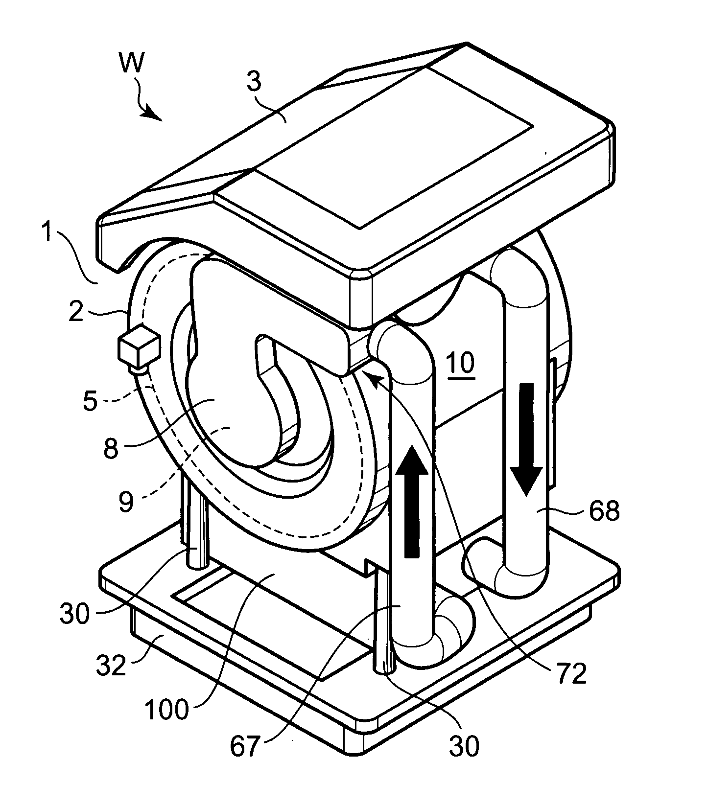
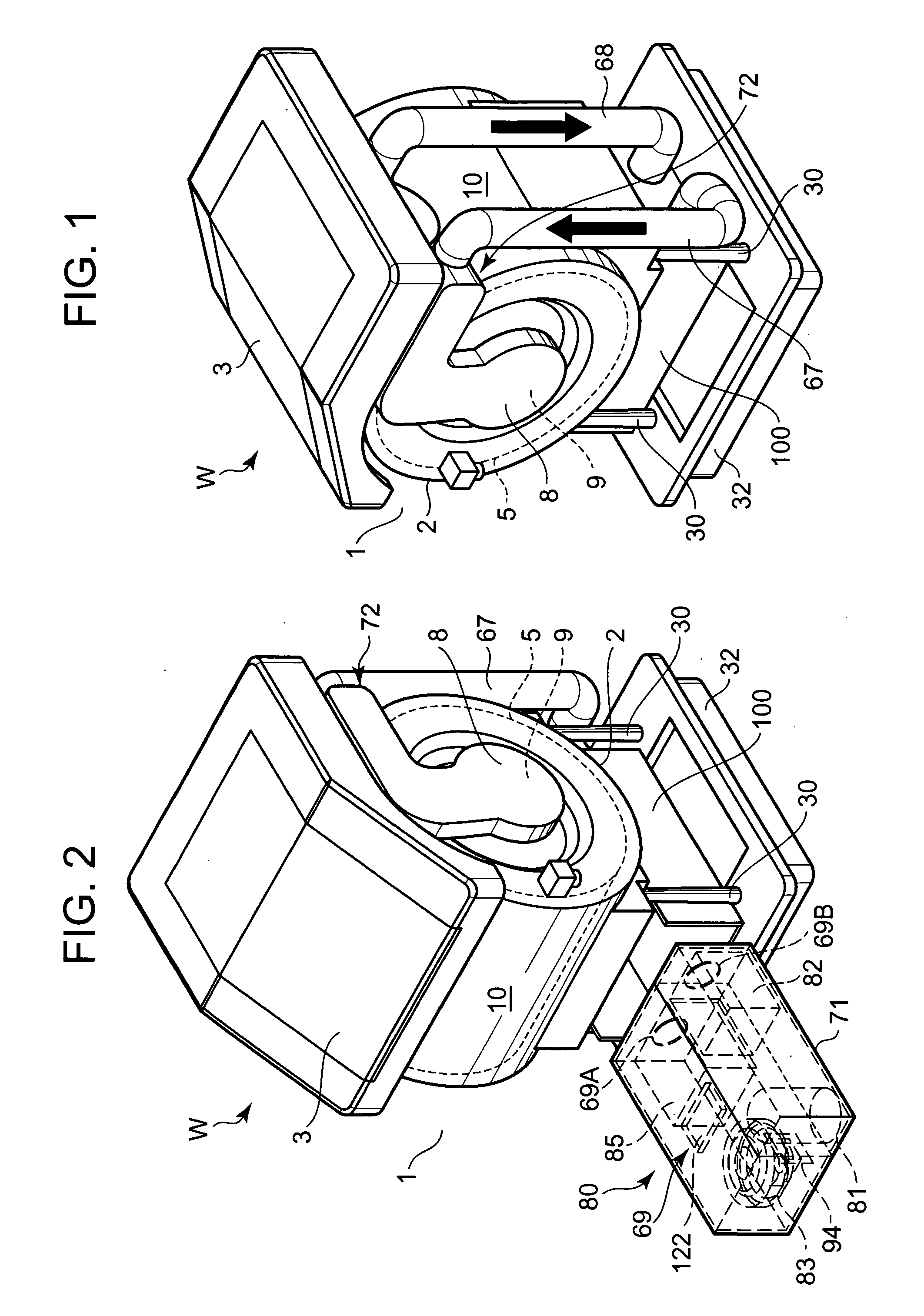
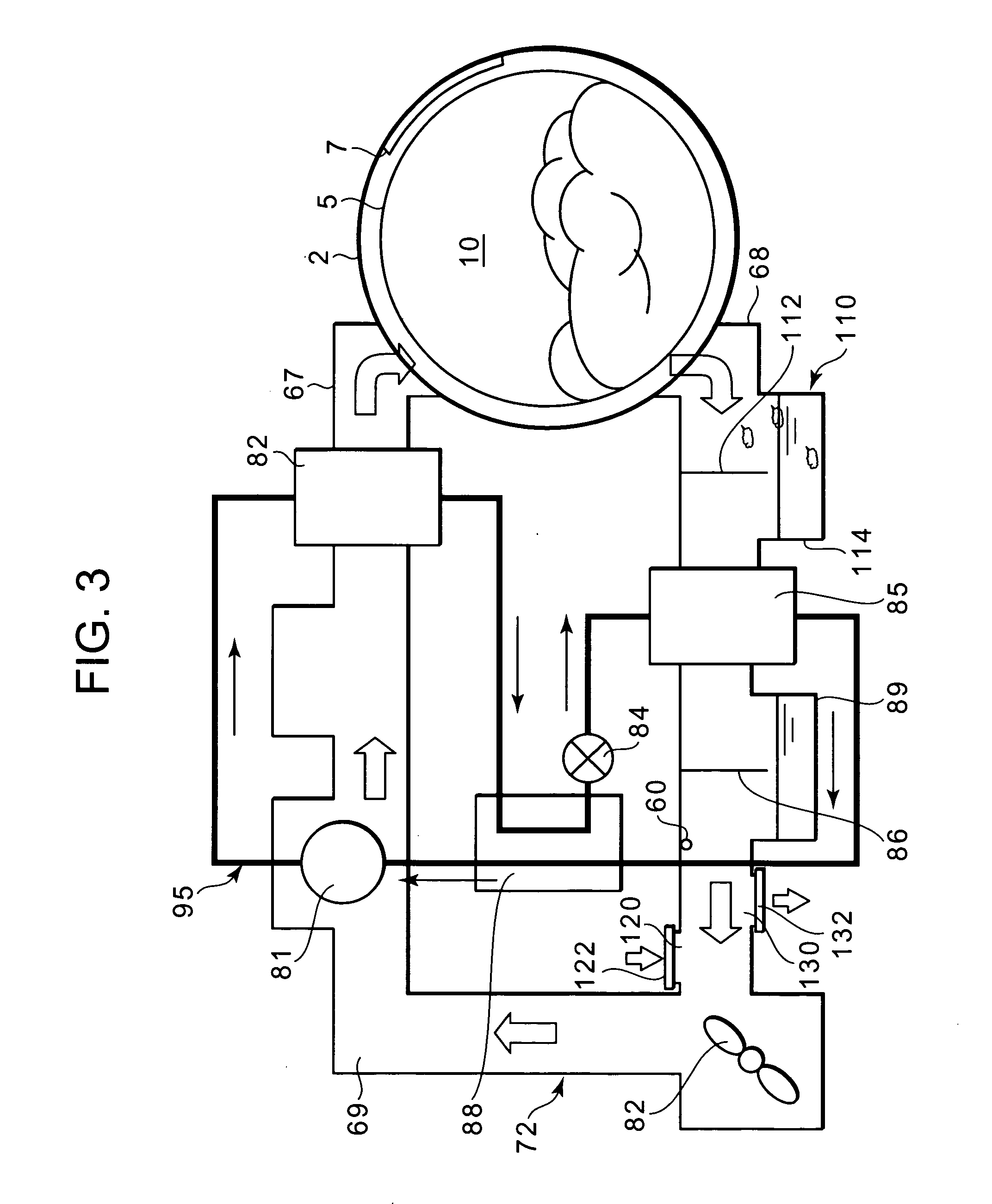
[0031]FIG. 1 is an inner constitution diagram of a washing / drying machine W which executes a washing operation and a drying operation after ending the washing operation according to an embodiment of a drying machine to which the present invention is applied, FIG. 2 is an inner constitution diagram of the washing / drying machine W in a state in which a duct box 71 is taken out, and FIG. 3 is a diagram showing flows of refrigerant and drying air of the washing / drying machine W. The washing / drying machine W of the present embodiment is used for washing and drying a matter to be washed such as clothing (this matter to be washed constitutes a matter to be dried in the drying operation). An open / close door 3 for inserting / removing the matter to be washed is attached to an upper surface middle part of a main body 1 (a case of the main body 1 is seen through in the drawing) forming an outer body. An operation panel (not shown) on which various operation switches and display portions are arra...

embodiment 2

[0085] Next, another embodiment of a drying machine to which the present invention is applied will be described with reference to FIG. 4. It is to be noted that in FIG. 4, components denoted with the same numerals as those of FIGS. 1 to 3 produce similar effects.

[0086] In FIG. 4, reference numeral 140 denotes an outside air introduction port in the present embodiment, and this outside air introduction port 140 is formed between a housing chamber 10 and an evaporator 85 and in a duct member 68 on an air downstream side of a waste thread removing device 110. This outside air introduction port 140 is a port for mixing outside air with air circulating in a air circulation path 72, and a lid member 142 is openably attached to an opening. Opening / closing and open degree of the lid member 142 are controlled by a control device in the same manner as in the above-described embodiment. That is, the control device controls the opening / closing and open degree of the lid member 142, and adjusts...


PUM


Abstract

An object is to provide a drying machine capable of maintaining air discharged into a housing chamber while efficiently drying a matter to be dried in a short time. A drying machine provided with a housing chamber which houses the matter to be dried, and executing a drying operation of the matter to be dried in the housing chamber comprises: a gas cooler; an evaporator; a blower fan; an air circulation path for discharging air heated by the gas cooler into the housing chamber by the blower fan, sending the air passed through the housing chamber into the evaporator, and circulating the air in the gas cooler; and a closable outside air introduction port for mixing outside air with the air circulating in the air circulation path.

Description

BACKGROUND OF THE INVENTION [0001] The present invention relates to a drying machine which comprises a housing chamber for housing a matter to be dried and which executes a drying operation of the matter to be dried in the housing chamber. [0002] In a drying machine, an electric heater or a gas burning heater has heretofore been used as a heat source, outside air is heated by the electric heater or the burning heater to thereby form the air at high temperature, thereafter the air is blown into a housing chamber in which a matter to be dried such as clothing is housed, and the matter to be dried in the housing chamber is dried. [0003] However, in the drying machine, since the electric heater, the gas burning heater or the like is used as a heat source, energy consumption for drying the matter to be dried increases, and there has been a problem that energy costs such as electricity and gas charges soar. [0004] To solve the problem, a clothing drying machine has been developed which a ...

Claims


Application Information

Patent Timeline
IPC IPC(8): D06F58/02F26B11/02F26B21/06
CPCD06F58/02D06F58/206D06F58/20
Inventor ONO, KOJITOMOCHIKA, KAZUYOSHI
Owner SANYO ELECTRIC CO LTD
Why Eureka
Try Eureka