Lighting apparatus using light emitting diodes

a technology of light-emitting diodes and led landscape lighting, which is applied in the direction of lighting and heating apparatus, lighting support devices, printing press parts, etc., can solve the problems of low efficiency of heat radiation, low maintenance cost, and difficulty in efficiently diffusing heat emitted from a number of high-brightness light-emitting diodes to the outside, so as to and maximize the heat radiation effect

Active Publication Date: 2012-08-30
AMOLUXE
View PDF7 Cites 72 Cited by
  • Summary
  • Abstract
  • Description
  • Claims
  • Application Information

AI Technical Summary

Benefits of technology

[0062]As described above, a lighting apparatus using light emitting diodes according to the present invention employs an air circulation path of making an air circulation using an atmospheric pressure difference between both side ends of the air circulation path that is lengthily formed at a central portion of a left-hand and right-hand heat radiation unit structure, to thereby maximize a heat radiation effect, when a bar-shaped flood lighting apparatus or a landscape lighting apparatus is made of a number of light emitting diodes (LEDs).
[0063]In addition, the lighting apparatus according to the present invention can maximize a heat radiation effect since a power supply is separately installed from a heat radiation unit or a heat radiation housing, and heat generated from the light emitting diodes and the power supply are simultaneously radiated through the air circulation path that is lengthily formed at the center of the housing and communicates with the outside.
[0064]Further, the lighting apparatus according to the present invention can make it easy to implement a variety of desired light distribution types of lighting apparatuses since a number of LED modules are mounted in an angle adjustment block so that the LEDs have a variety of angles, respectively.
[0065]In addition, the lighting apparatus according to the present invention provides a dual heat radiation structure, to thereby maximize a heat radiation effect, in which heat radiation fins are formed on both side surfaces of the lighting apparatus to thereby increase surface areas of the heat radiation fins, and to simultaneously provide an air circulation path.

Problems solved by technology

In addition, the LEDs consume less electric power, to thereby save a maintenance cost.
However, the LED landscape lighting apparatus has a problem of having no effective heat radiation because the light emitting module including a light emitting diode, a printed circuit board (PCB), and a controller is disposed in the unit body of the lighting unit, and end covers are combined on both sides of the unit body in order to protect the light emitting module, with a result that the inner portion of the unit body is maintained to be in a sealed state.
In other words, the LED landscape lighting apparatus has the difficulty in efficiently diffusing heat emitted from a number of high brightness light emitting diodes to the outside.
As a result, the LED landscape lighting apparatus may cause problems that degrade light emission efficiency by the heat, as well as that damages parts of the LED landscape lighting apparatus.
However, since the LED lighting apparatus disclosed in the Korean Patent No. 10-0903305 employs a structure of sealing the inner portion of the main body with the brackets, heat that is diffused downwards from the LED and lens portion is not effectively radiated.
However, such a heat radiation fin structure has a problem of decreasing a heat radiation effect.
Accordingly, heat that is generated in the inside of the unit may not be efficiently discharged out.

Method used


Image

  • Lighting apparatus using light emitting diodes
  • Lighting apparatus using light emitting diodes
  • Lighting apparatus using light emitting diodes

Examples


first embodiment

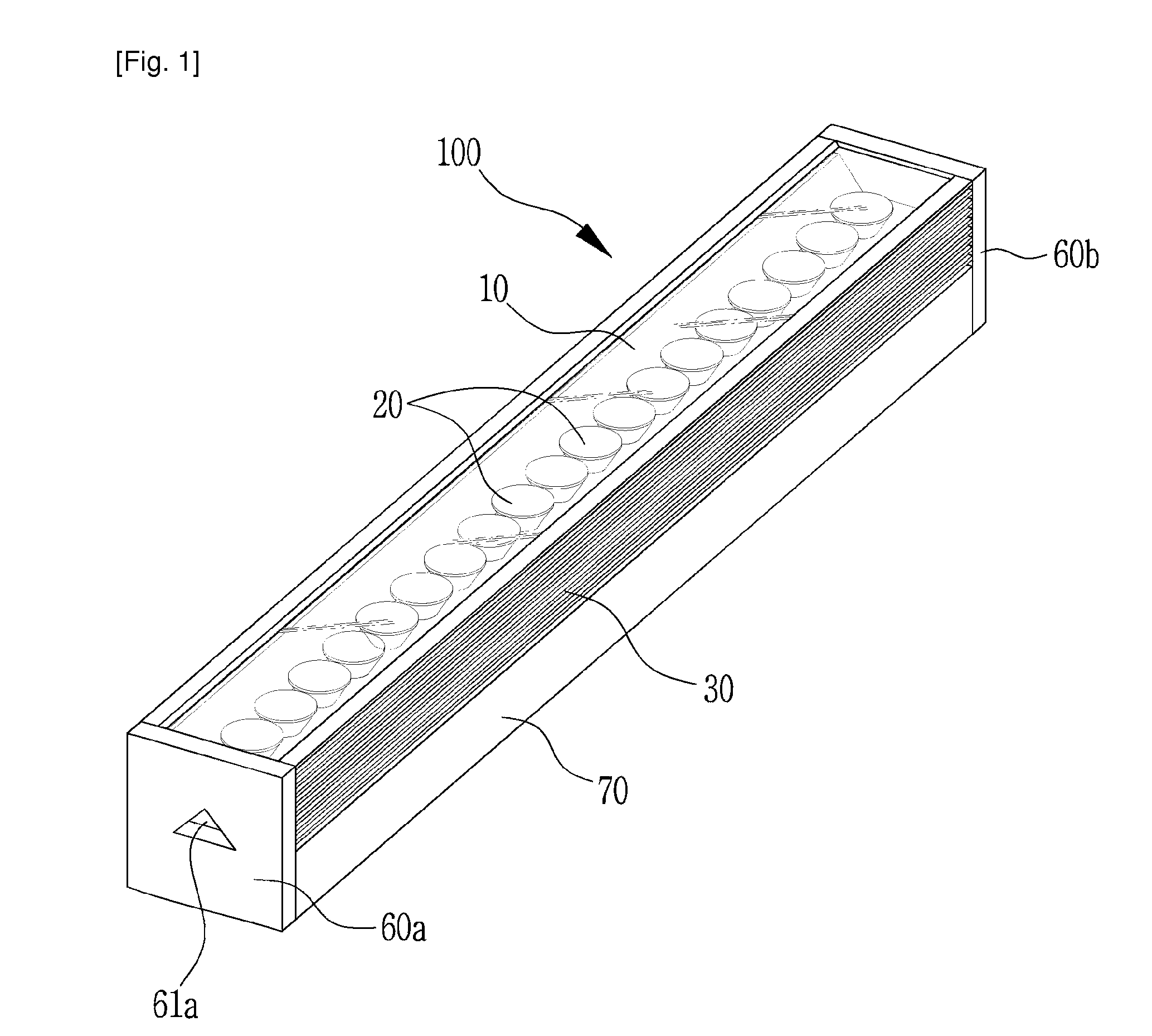
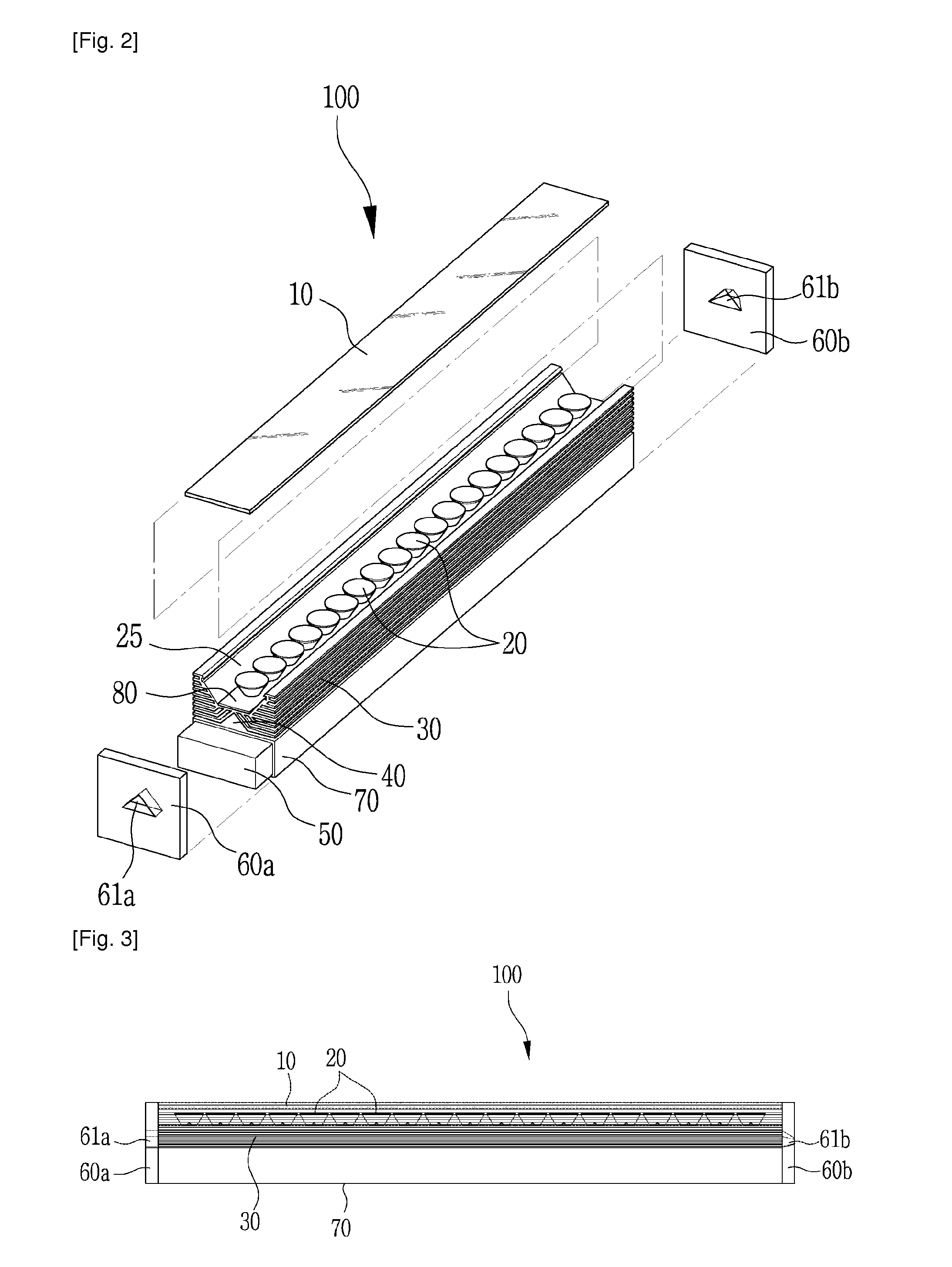
[0085]FIGS. 1 to 3 are a perspective view, a disassembled perspective view, and a side sectional view, respectively which show a lighting apparatus using light emitting diodes according to the present invention.

[0086]The lighting apparatus 100 using light emitting diodes according to the first embodiment of the present invention may be used as for example a landscape lighting apparatus that is fixedly installed on a floor or wall of a building so as to elegantly illuminate the external appearance of the building. However, the lighting apparatus 100 according to the present invention can be applied to an indoor or outdoor parking lot illumination device, an indoor illumination device, a tunnel illumination device, and a street lighting apparatus, as well as a landscape lighting apparatus.

[0087]Referring to FIGS. 1 to 3, the lighting apparatus 100 includes: a rectangular vessel shaped housing 70; a heat radiation unit 30 that forms an LED module accommodation groove on top of the hous...

second embodiment

[0109]FIGS. 5A and 5B are a perspective view and a cross-sectional view respectively showing a lighting apparatus using light emitting diodes according to the present invention.

[0110]Referring to FIGS. 5A and 5B, according to a difference between the first and second embodiments of the present invention, the heat radiation unit 30 is formed of a left and right symmetrical structure in the first embodiment case, but a heat radiation unit 300 is formed of a left and right asymmetrical structure in the second embodiment case. In particular, an LED module accommodation groove 29 that accommodates LED modules 20b is formed of an inclined surface 25a of a curved shape and an inclined surface 25b of a planar shape. The LED modules 20b are mounted on the inclined surface 25b of the planar shape.

[0111]In this case, the inclined surface 25a of the curved shape acts as a reflective surface, and an inclination angle of the inclined surface 25b of the planar shape on which the LED modules 20b ar...

third embodiment

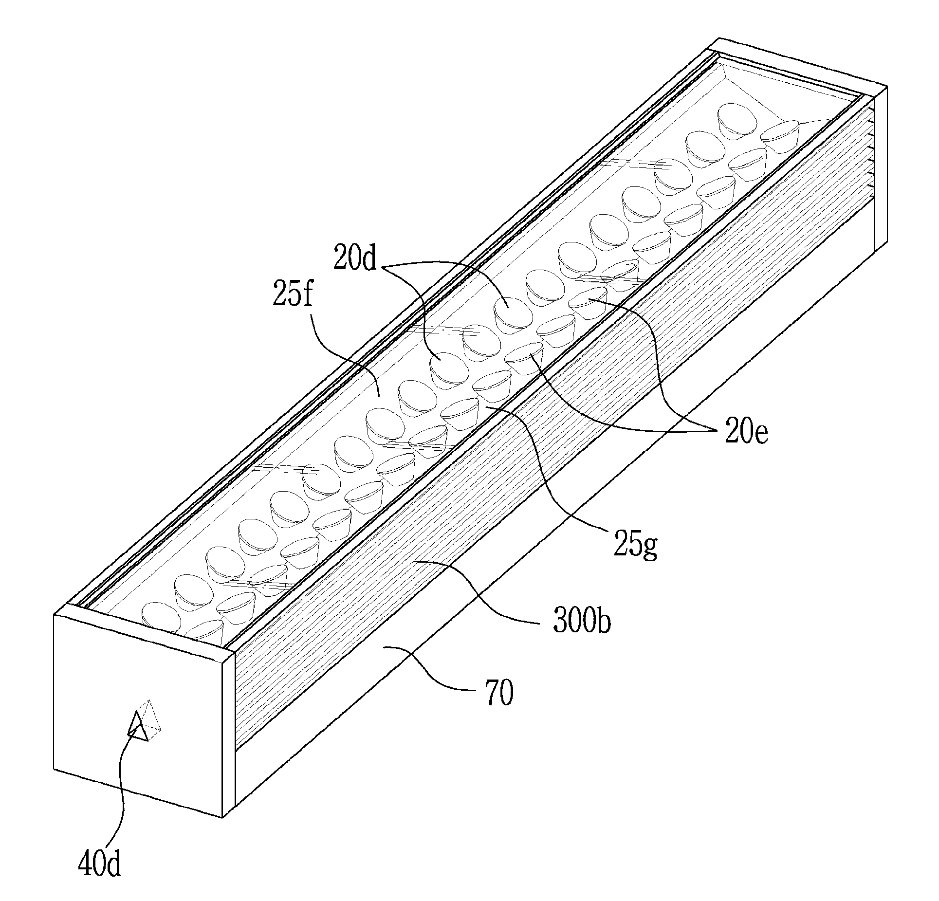
[0112]FIGS. 6A and 6B are a perspective view and a cross-sectional view respectively showing a lighting apparatus using light emitting diodes according to the present invention.

[0113]Referring to FIGS. 6A and 6B, an LED module accommodation groove 29 formed by a heat radiation unit 300a is formed of a vertical surface 25e at one side of the LED module accommodation groove 29, and an inclined surface 25d of a substantially 45 degrees from the horizontal plane at the other side thereof in which the vertical surface 25e faces the inclined surface 25d. LED modules 20c are mounted on the inclined surface 25d. Since the vertical surface 25e has low reflection efficiency, a reflective plate 25c of a curved shape is additionally disposed along a light reflection path of the LED modules 20c so that light emitted from the LED modules 20c can be reflected. Thus, a light distribution angle of the LED modules 20c can be adjusted on the basis of the angle of the inclined surface 25d and the refle...


PUM


Abstract

Provided is a lighting apparatus using light emitting diodes (LEDs) having a lateral heat radiation unit structure that can maximize heat radiation effect by employing an air vent structure causing atmospheric pressure difference between both side ends of an air circulation path. The lighting apparatus comprising a housing having a power supply accommodation space therein, a heat radiation unit that comprises an LED module accommodation groove that is installed on the top of the housing and having at least one inclined surface or mounting surface on which the LED module is mounted, and a number of fins that are formed on the outer circumferential surface of the LED module accommodation groove, an air circulation path that is lengthily formed between the housing and the heat radiation unit.

Description

TECHNICAL FIELD[0001]The present invention relates to a lighting apparatus using light emitting diodes, and more particularly, to a lighting apparatus using light emitting diodes having a lateral heat radiation unit structure that can maximize a heat radiation effect by employing an air vent structure that achieve an air circulation using an atmospheric pressure difference between both sides of an air circulation path that is formed at a heat radiation housing structure.BACKGROUND ART[0002]A variety of conventional light sources such as fluorescent lamps, neon lamps and halogen lamps have preoccupied in the market of flood lamps, landscape lamps, and advertising lamps. However, light emitting diodes (LEDs) are in the spotlight of consumers as light sources in the lamp market in recent years. The reason why LEDs are getting the spotlight in the field of light sources is due to the device characteristics of the LEDs.[0003]The conventional light sources that emit light using mercury ar...

Claims


Application Information

Patent Timeline
Patent Type & Authority Applications(United States)
IPC IPC(8): F21V1/00F21V21/00F21V29/505
CPCF21S4/008F21V15/015F21V21/30F21V29/004F21Y2101/02F21V29/83F21V29/505F21V29/507F21V29/745F21V29/75F21V29/77F21Y2103/003F21V29/74F21S4/28F21Y2103/10F21Y2115/10B41F23/08
Inventor GILL, JASON JAE
Owner AMOLUXE
Why Eureka
Try Eureka