Low energy electric air cycle with portal shroud cabin air compressor

a low-energy, air-cycle technology, applied in the direction of energy-efficient board measures, domestic cooling devices, lighting and heating devices, etc., can solve the problems of air cycle machines, large number of components in a typical environmental control system, and large amount of energy to opera

Inactive Publication Date: 2007-05-24
HONEYWELL INT INC
View PDF9 Cites 73 Cited by
  • Summary
  • Abstract
  • Description
  • Claims
  • Application Information

AI Technical Summary

Benefits of technology

[0005] The present invention provides an environmental control system for an aircraft cabin. The environmental control system comprises a plurality of electrically-driven cabin air compressors, each cabin air compressor compressing ram air received from the aircraft exterior; a heat exchange circuit comprising a primary heat exchanger and a secondary heat exchanger in series, the primary heat exchanger adapted to receive airflow from at least one of the cabin air compressors, and the secondary heat exchanger adapted to supply airflow to the aircraft cabin; and an air cycle machine comprising a compressor, adapted to receive airflow from the primary heat exchanger and supply compressed air to the secondary heat exchanger. At least one of the cabin air compressors comprises a housing having an air inlet, and an air outlet in communication with the primary heat exchanger, the air inlet defining an outer circular wall, an inner circular shroud wall having at least one port extending therethrough, a central channel, and an annular channel dispose...

Problems solved by technology

The numerous applications and components in a typical environmental control system, including the ram air cycle, the recirculation cycle, heat exchangers, condensers, reheaters, water ext...

Method used


Image

  • Low energy electric air cycle with portal shroud cabin air compressor
  • Low energy electric air cycle with portal shroud cabin air compressor
  • Low energy electric air cycle with portal shroud cabin air compressor

Examples


Embodiment Construction

[0012] The following detailed description of the invention is merely exemplary in nature and is not intended to limit the invention or the application and uses of the invention. Furthermore, there is no intention to be bound by any theory presented in the preceding background of the invention or the following detailed description of the invention.

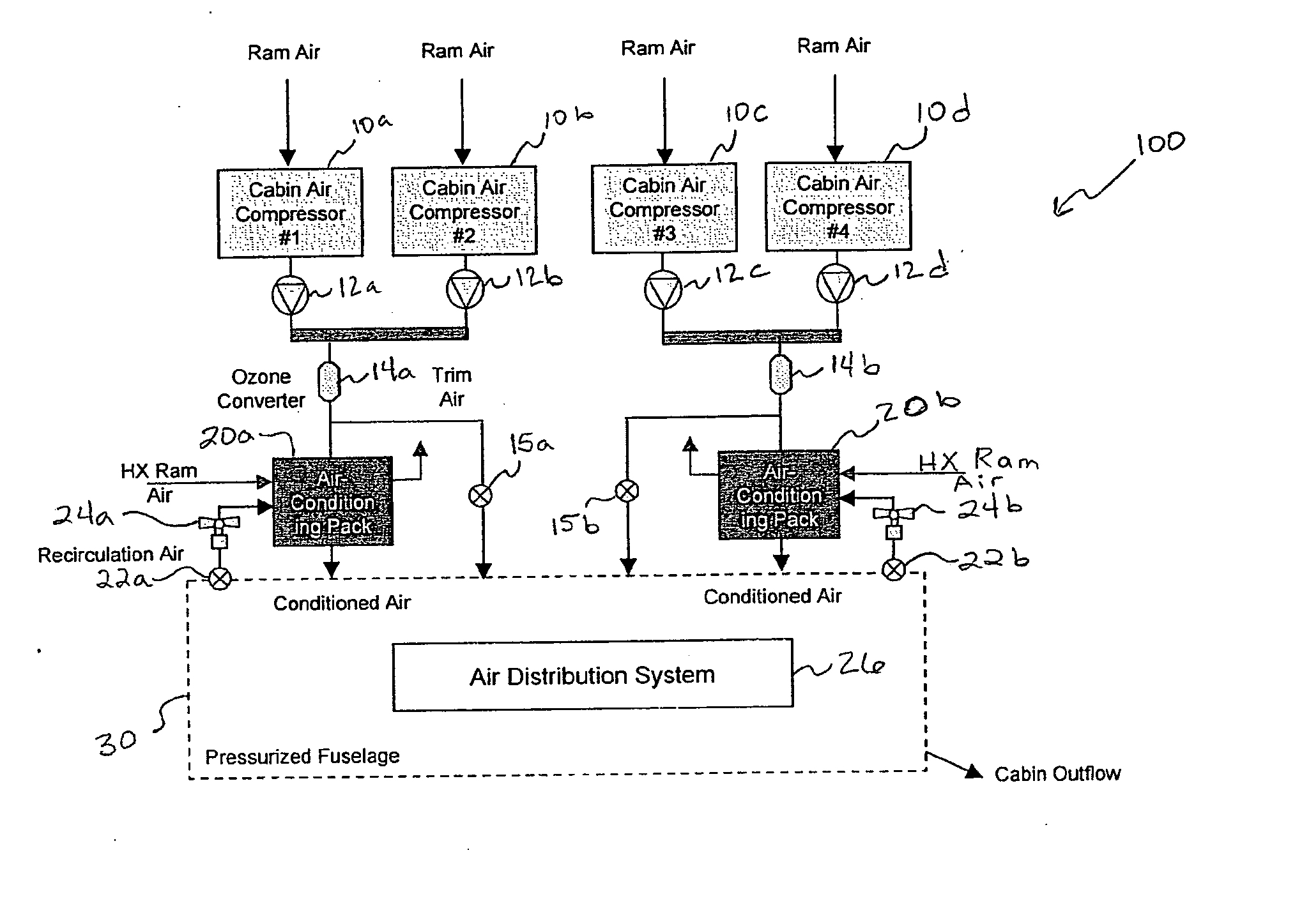
[0013] Turning now to the figures, FIG. 1 is a flow chart illustrating the top-level architecture of an exemplary environmental control system 100 for an aircrew cabin or other area in an aircraft fuselage 30. The illustrated system 100 includes four electrically-driven cabin air compressors 10a-10d, each receiving fresh ram air from inlets that are located in at least one favorable position near the aircraft's forward belly fairing leading edge. Although there are four compressors 10a-10d in the illustrated embodiment, a system that incorporates fewer compressors may still be used without departing from the scope of the present invention....


PUM


Abstract

An environmental control system for an aircraft cabin includes a plurality of electrically-driven ported shroud cabin air compressors, each cabin air compressor compressing ram air received from the aircraft exterior, a heat exchange circuit comprising a primary heat exchanger receiving airflow from at least one of the cabin air compressors, and the secondary heat exchanger supplying airflow to the aircraft cabin, and an air cycle machine comprising a compressor adapted to receive airflow from the primary heat exchanger and supply compressed air to the secondary heat exchanger. The environmental control system may further comprise an air recirculation system, having an aft recirculation fan adapted to receive a portion of recirculation air from the aircraft cabin, and a recirculation heat exchanger, disposed in the heat exchange circuit in series with the primary and secondary heat exchangers, and adapted to receive airflow from the aft recirculation fan.

Description

CROSS-REFERENCES TO RELATED APPLICATIONS [0001] This application claims the benefit of U.S. Provisional Application No. 60 / 604,610 filed Aug. 25, 2004.TECHNICAL FIELD [0002] The present invention relates to environmental control systems for various aircrafts. More particularly, the present invention relates to electrically-driven air cycle systems that regulate the temperature of at least the aircraft fuselage. BACKGROUND [0003] Passenger aircrafts are typically equipped with an environmental control system, including an air cycle conditioning system for cooling the aircrew cabins, and other aircraft locations and components. One class of air cycle conditioning systems that are widely used in aircraft to provide cooled air takes advantage of a supply of pressurized air that is bled from an aircraft engine, known as bleed air. Other electrically-driven environmental control systems generally operate by receiving fresh ram air from inlets that are located in at least one favorable pos...

Claims


Application Information

Patent Timeline
IPC IPC(8): F25D9/00
CPCB64D13/02B64D13/06B64D2013/0618B64D2013/064B64D2013/0644F25B9/004Y02T50/44Y02T50/56Y02T50/40Y02T50/50
Inventor CLAEYS, HENRY M.CLARKE, KATHERINEELPERN, DAVID G.
Owner HONEYWELL INT INC
Why Eureka
Try Eureka