Drying unit and laundry washing/drying machine equipped with the drying unit

a drying unit and laundry technology, applied in the field of drying units, can solve the problems of inability to quickly heat deficiency of heat within the air circulation path, and inability to quickly raise the drum inlet air temperature to a sufficiently high temperature, so as to shorten the drying operation time, prevent excessive accumulation of heat, and increase the speed of temperature rise of circulation air

Active Publication Date: 2008-10-02
QINGDAO HAIER WASHING MASCH CO LTD +1
View PDF3 Cites 77 Cited by
  • Summary
  • Abstract
  • Description
  • Claims
  • Application Information

AI Technical Summary

Benefits of technology

[0029]According to the above sixth aspect of the present invention, since the auxiliary heat exchanger is forcibly heat-exchanged with the ambient air present outside the air circulation path by the blower, not only the same effect as in the above fifth aspect is attained but also the desired object can be achieved by the addition of a simple device.
[0030]According to the above seventh aspect of the present invention, the auxiliary heat exchanger is heat-exchanged with the antifreeze solution stored in the antifreeze solution tank, whereby not only the same effect as in the above fifth aspect is attained but also the desired object can be achieved by the addition of a simple device.
[0031]According to the above eighth aspect of the present invention, in a laundry washing machine wherein washing, rinsing, spin-drying and drying operation (drying process) of the laundry are performed within a rotary drum, rinsing water is stored in a water storage tank. Moreover, the heat pump cycle device constitutes a refrigerant circuit so that the refrigerant leaving the radiator passes through both pressure reducing/expansion device and auxiliary heat exchanger and this auxiliary heat exchanger undergoes heat exchange with the water stored in the water storage tank, whereby the circulation air cooling capacity of the evaporator installed within the air circulation path is deteriorated. Consequently, the air temperature at the evaporator outlet, i.e., at the radiator inlet, rises and so does the air temperature at the radiator outlet. As a result, in case of performing the laundry drying operation (drying process) by the heat pump cycle device, it is possible to increase the speed of temperature rise of the circulation air in an initial stage of the drying operation (drying process) (e.g. for 20 minutes after start of the drying operation) and hence possible to shorten the time of the drying operation (drying process). Further, the power consumption in the drying operation (drying process) performed by the heat pump cycle device, etc. is reduced.
[0032]According to the above ninth aspect of the present invention, since the refrigerant leaving the radiator passes through the pressure reducing/expansion device and the auxiliary heat exchanger and thereafter flows from the pressure reducing/expansion valve to the evaporator, there can be attained the same effects as in the above fifth to eighth aspects. In a middle stage of the drying operation (drying process) (e.g. for 30 minutes after the lapse of 20 minutes after start of the drying operation) substantially at a predetermined high temperature (e.g. 60° C. to 85° C.) or a temperature close thereto as a circulation air temperature increased by the initial stage of drying operation (drying process), there is performed a normal operation in which the refrigerant leaving the radiator bypasses the pressure reducing/expansion device and the auxiliary heat exchanger and flows through the pressure reducing/expansion valve to the evaporator, making it possible to perform the drying operation (drying process) at a predetermined high temperature (e.g. 60° C. to 85° C.). In a latter stage of the drying operation (drying process) (e.g. for 40 minutes after the lapse of 50 minutes after start of the drying operation), whether the auxiliary heat exchanger is to be bypassed or act as a radiator for the water stored in the water storage tank is switched from one to the other intermittently at a certain duty ratio, thereby radiating a certain quantity of heat to water to prevent

Problems solved by technology

However, in an initial state of the drying operation (in an initial stage of the drying process), the drum inlet air temperature cannot be raised quickly to a sufficiently high temperature (e.g. 70° C. or so) because the heat within the air circulation path is deficient.
Thus, when performing the heat pump cycle to effect drying, in an initial stage

Method used


Image

  • Drying unit and laundry washing/drying machine equipped with the drying unit
  • Drying unit and laundry washing/drying machine equipped with the drying unit
  • Drying unit and laundry washing/drying machine equipped with the drying unit

Examples


first embodiment

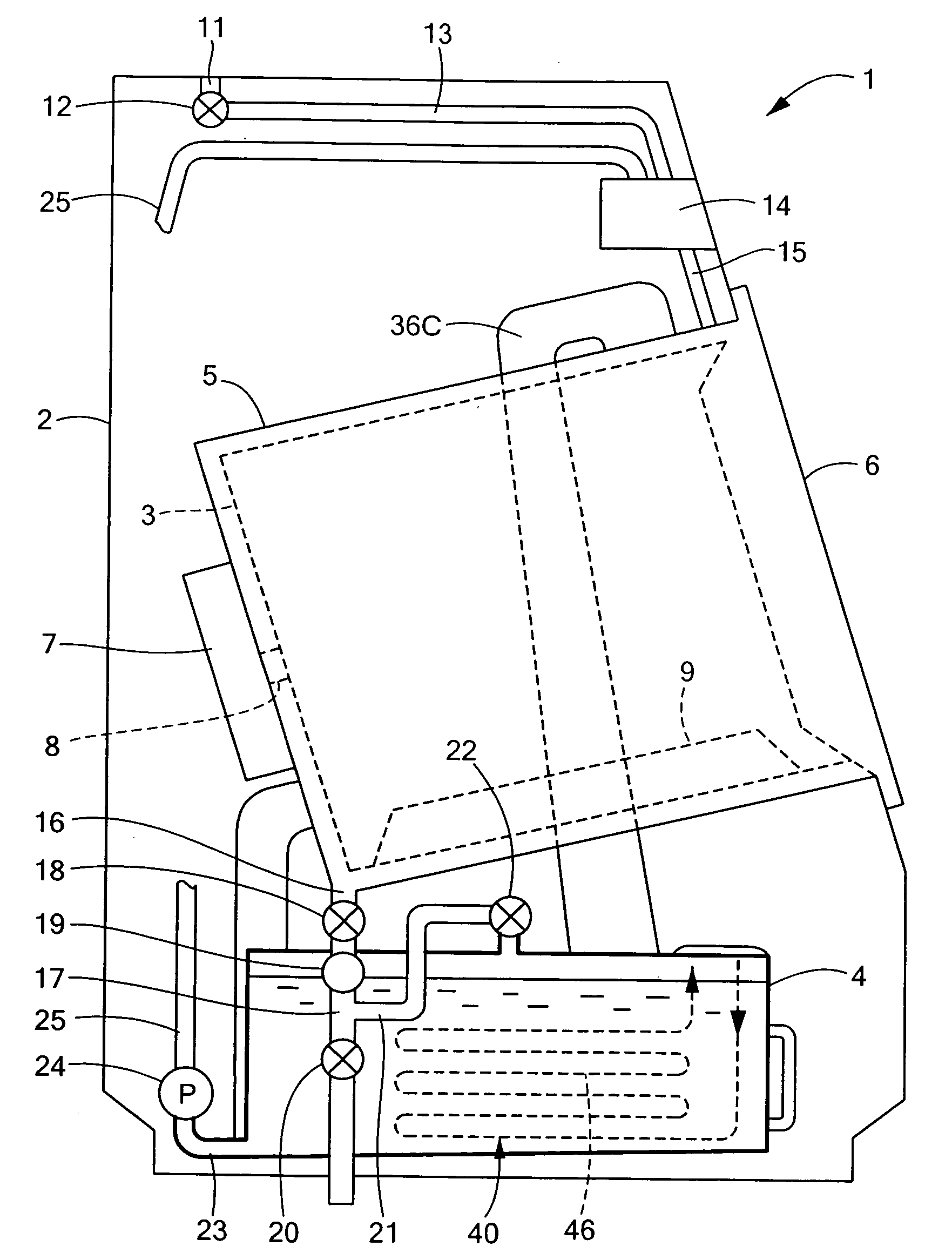
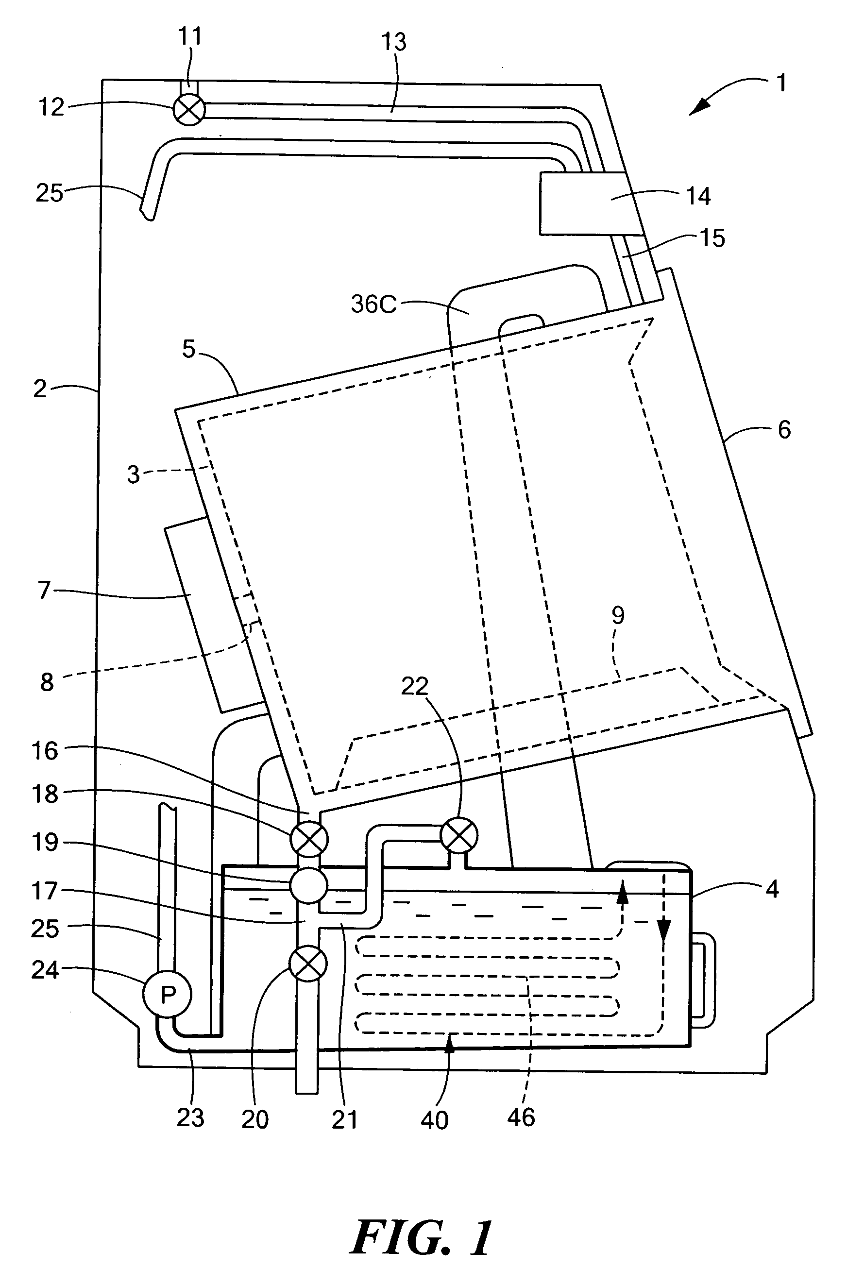
[0044]As a first embodiment of the present invention, a description will be given below about a construction in which a drying unit according to the present invention is applied to a laundry washing / drying machine 1 which performs washing, rinsing, spin-drying and drying of the laundry within a rotary drum 3. FIG. 1 is a vertically sectional left side view showing schematically an internal construction of a laundry washing / drying machine equipped with a drying unit according to the present invention, FIG. 2 is a vertically sectional right side view thereof, FIG. 3 is a diagram showing an air circulation path in the drying unit, and FIG. 4 is a time chart showing operations of various components of the laundry washing / drying machine.

[0045]In FIG. 1, in a laundry washing / drying machine 1 equipped with a drying unit 50 according to the present invention, a shell of the machine is defined by a housing 2, a rotary drum 3 is disposed centrally of the housing 2, a water storage tank 4 is d...

second embodiment

[0072]Next, a second embodiment of the present invention will be described. FIG. 5 shows an air circulation path in a drying unit 50 according to a second embodiment of the present invention. An internal construction of a laundry washing / drying machine using this drying unit 50 corresponds substantially to an internal construction wherein the heat pump cycle device shown in FIGS. 1 and 2 is replaced by a heat pump cycle device 35 in an air circulation path shown in FIG. 5. As to a time chart showing operations of various components of the laundry washing / drying machine, it is the same as that of FIG. 4 and therefore an explanation thereof is as given in the first embodiment.

[0073]In the air circulation path of the drying unit 50 according to the present invention which is shown in FIG. 5, the same functional portions as in the first embodiment are denoted by the same reference numerals as in the first embodiment. It is the heat pump cycle device 35 that is a difference of this secon...

third embodiment

[0089]A third embodiment of the present invention will now be described. This third embodiment adopts a second pressure reducing / expansion valve 45A instead of the capillary tube 45 as the pressure reducing / expansion device used in the second embodiment. FIG. 8 illustrates an air circulation path formed in a drying unit 50 according to a third embodiment of the present invention. An internal construction of a laundry washing / drying machine using this drying unit 50 corresponds to an internal construction wherein the heat pump cycle device 35 shown in FIGS. 1 and 2 is replaced by a heat pump cycle device disposed in the air circulation path shown in FIG. 8. As to a time chart showing operations of various components of the laundry washing / drying machine, it is the same as that shown in FIG. 4 and therefore an explanation thereof is as given in the first embodiment.

[0090]In the air circulation path of the drying unit 50 according to this third embodiment which is shown in FIG. 8, the ...


PUM


Abstract

In a laundry washing/drying machine involving drying by a heat pump cycle, in an initial stage of the drying operation the heat within an air circulation path is deficient and therefore it is impossible to effect quick heating of air on a drum inlet side up to a sufficiently high temperature. According to the present invention there is provided a drying unit capable of raising the drum inlet air temperature quickly up to a sufficiently high temperature in an initial stage of the drying operation and thereby shortening the drying time. The drying unit includes a heat pump cycle device for performing a cycle of radiating, with use of a radiator, the heat of a refrigerant compressed by a compressor, passing the refrigerant through a pressure reducing/expansion valve, evaporating the refrigerant in an evaporator and compressing the refrigerant again by the compressor, an air circulation path for allowing air to be circulated by a blower in such a manner that air heated by the radiator is introduced into a drying chamber to dry the laundry, exhaust air discharged from the drying chamber is passed through the evaporator, then is heated again by the radiator and the air thus dehumidified is circulated by the blower, and an external heat source applying device for applying the heat of an external heat source to the evaporator to quicken the rise in temperature of the air in an initial stage of the drying operation.

Description

BACKGROUND OF THE INVENTION[0001]1. Field of the Invention[0002]The present invention relates to a drying unit comprising a heat pump cycle device and an air circulation path, the heat pump cycle device performing a cycle of radiating, with use of a radiator, the heat of a refrigerant compressed by a compressor, then allowing the refrigerant to pass through a pressuring reducing / expansion unit and be evaporated by an evaporator, then compressing the refrigerant again by the compressor, the air circulation path allowing air to be circulated by a blower in such a manner that the air heated by the radiator is introduced into a drying chamber to dry the laundry, then the air exhausted from the drying chamber is dehumidified by the evaporator and is thereafter heated again by the radiator, as well as a laundry washing / drying machine equipped with the drying unit.[0003]2. Description of the Prior Art[0004]There is known a laundry washing / drying machine equipped with a drying unit, the dry...

Claims


Application Information

Patent Timeline
IPC IPC(8): F26B21/02F26B21/06F26B21/08B08B3/00F26B21/00
CPCD06F58/206D06F25/00D06F39/04D06F33/52D06F34/26D06F2103/32D06F2105/32D06F2105/36Y02B40/00
Inventor KUWABARA, OSAMU
Owner QINGDAO HAIER WASHING MASCH CO LTD
Why Eureka
Try Eureka