Integrated high thermal conductive fiber as cooling fin for sma actuator with expandable sleeve

a technology of expandable sleeve and high thermal conductivity, which is applied in the direction of machines/engines, light and heating apparatus, transportation and packaging, etc., can solve the problems of insufficient cooling rate, unsatisfactory cooling time, and limited cycle and/or response time of sma actuators, etc., to facilitate the expansion of the expandable sleeve radial, increase the cooling rate of the torque tube, and facilitate the removal of heat

Active Publication Date: 2016-07-14
THE BOEING CO
View PDF6 Cites 9 Cited by
  • Summary
  • Abstract
  • Description
  • Claims
  • Application Information

AI Technical Summary

Benefits of technology

[0007]Aspects of the present disclosure generally relate to an SMA actuator that includes a cooling device that may be disposed within a torque tube. The cooling device may include a sliding sleeve, an expandable sleeve, and plurality of cooling fins coupled to the expandable sleeve. Axial movement of the sliding sleeve relative to the expandable sleeve facilitates radial expansion of the expandable sleeve and urges the cooling fins into contact with the torque tube. The cooling fins function as heat sinks when in contact with the torque tube to facilitate the removal of heat from the torque tube thereby increasing the cooling rate of the torque tube. During heating of the torque tube, the cooling fins may be spaced apart from the torque tube to reduce the thermal mass that is heated, thus increasing the heating rate of the torque tube.

Problems solved by technology

Conventional SMA actuators are capable of being rapidly heated, however, satisfactory cooling times have posed challenges.
The unsatisfactory cooling times have limited the cycle and / or response time of the SMA actuator.
Additionally, cooling rates may be insufficient when the actuator is responsible for moving heavy or large components.
The higher thermal mass of the SMA cannot be cooled at a fast enough rate to move the larger component at desired speeds.

Method used


Image

  • Integrated high thermal conductive fiber as cooling fin for sma actuator with expandable sleeve
  • Integrated high thermal conductive fiber as cooling fin for sma actuator with expandable sleeve
  • Integrated high thermal conductive fiber as cooling fin for sma actuator with expandable sleeve

Examples


Embodiment Construction

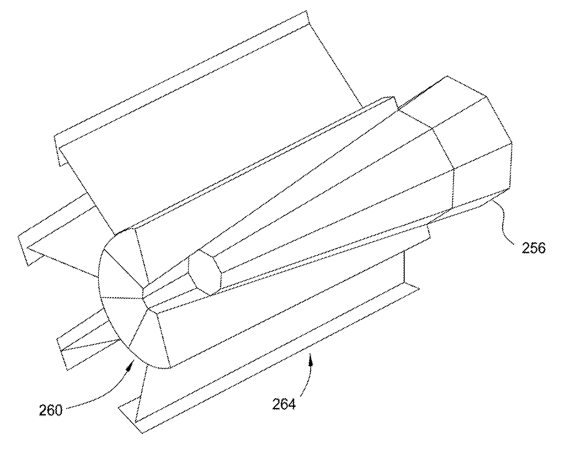
[0022]Aspects of the present disclosure generally relate to an SMA actuator that includes a cooling device disposed within a torque tube. In one aspect, the cooling device may include a sliding sleeve, an expandable sleeve, and plurality of cooling fins coupled to the expandable sleeve. Axial movement of the sliding sleeve relative to the expandable sleeve facilitates radial expansion of the expandable sleeve and urges the cooling fins into contact with the torque tube. The cooling fins function as heat sinks when in contact with the torque tube to facilitate the removal of heat from the torque tube thereby increasing the cooling rate of the torque tube. During heating of the torque tube, the cooling fins may be spaced apart from the torque tube to reduce the thermal mass that is heated, thus increasing the heating rate of the torque tube.

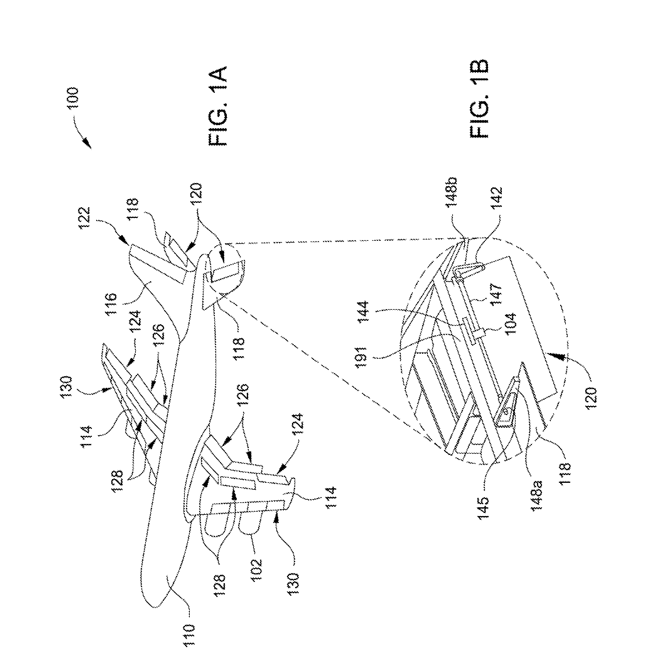
[0023]FIG. 1A schematically illustrates an aircraft 100 according to one aspect of the disclosure. FIG. 1B schematically illustrates an enlarged p...


PUM

PropertyMeasurementUnit
tensile strengthaaaaaaaaaa
densityaaaaaaaaaa
tensile strengthaaaaaaaaaa

Abstract

Aspects of the present disclosure generally relate to an SMA actuator that includes a cooling device disposed within a torque tube. In one aspect, the cooling device includes a sliding sleeve, an expandable sleeve, and plurality of cooling fins coupled to the expandable sleeve. Axial movement of the sliding sleeve relative to the expandable sleeve facilitates radial expansion of the expandable sleeve and urges the cooling fins into contact with the torque tube. The cooling fins function as heat sinks when in contact with the torque tube to facilitate the removal of heat from the torque tube to increase the cooling rate of the torque tube. During heating of the torque tube, the cooling fins may be spaced apart from the torque tube to reduce the thermal mass that is heated, thus increasing the heating rate of the torque tube.

Description

BACKGROUND[0001]1. Field[0002]Aspects of the present disclosure generally relate to a shape-memory alloy (SMA) actuator and a cooling device having increased cooling efficiency.[0003]2. Description of the Related Art[0004]An SMA is an alloy that “remembers” its original shape and that when deformed returns to its pre-deformed shape when heated. Actuation of the SMA can be effected through heating and cooling of the SMA. In one example, an SMA actuator may include a torque tube that rotates in a first direction when the torque tube is heated, and rotates in a second direction when the torque tube cools. The rate of heating and cooling (measured in degrees of rotation per second) controls the rate of movement of the SMA actuator. The rate of heating can be controlled by controlling a heater, and the rate of cooling may depend on ambient conditions or a fluid flow.[0005]Conventional SMA actuators are capable of being rapidly heated, however, satisfactory cooling times have posed challe...

Claims


Application Information

Patent Timeline
Patent Type & Authority Applications(United States)
IPC IPC(8): F03G7/06F28F13/00F28F21/06B64C13/28F28F21/02
CPCF03G7/065B64C13/28F28F13/00F28F21/06F28F21/02B64C13/30Y02T50/40
Inventor APDALHALIEM, SAHRUDINESHOME, MOUSHUMIMEREDITH, KIMBERLY D.ASHMAWI, WAEIL M.SAFAI, MORTEZACALKINS, FREDERICK T.
Owner THE BOEING CO
Why Eureka
Try Eureka