Filter element positioning cylinder

A positioning cylinder and filter element technology, applied in the field of purifiers, can solve the problems of weak fixing tightness and easy to loose, and achieve the effects of simple, fast and stable locking process, convenient operation, and improved assembly efficiency.

Active Publication Date: 2021-10-29
吴联星
View PDF9 Cites 0 Cited by
  • Summary
  • Abstract
  • Description
  • Claims
  • Application Information

AI Technical Summary

Problems solved by technology

[0002] The patent document with the notification number CN206467094U discloses a filter element layout waterway structure. The scheme recorded in this document mainly adopts the filter element water purification unit distributed in an array of 3 lining brackets for the filter element, and the filter element purification unit is cylindrical. , The filter element water purification unit is positioned and locked through the inner lining shell. The inner lining shell is integrally formed. The fixing tightness between the inner lining shell and the filter element purification unit is not firm, and it is easy to loosen during use.

Method used


Image

  • Filter element positioning cylinder
  • Filter element positioning cylinder
  • Filter element positioning cylinder

Examples


Embodiment

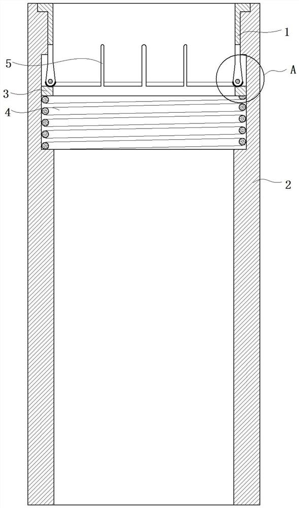
[0030] Such as figure 1 As shown, the embodiment of the present invention includes a cylinder body 2 and a locking cylinder 1,

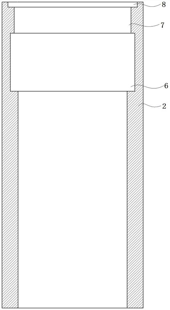
[0031] combine image 3 As shown, the cylinder body 2 is set through up and down, the upper port of the cylinder body 2 is provided with a stepped hole 7, the upper port of the stepped hole 7 is also provided with a counterbore 8, and the outer wall of the upper end of the locking cylinder 1 is provided with a limit platform 9, the limit The platform 9 is located in the counterbore 8, and the bottom side wall of the stepped hole 7 is surrounded by a limiting groove 6;

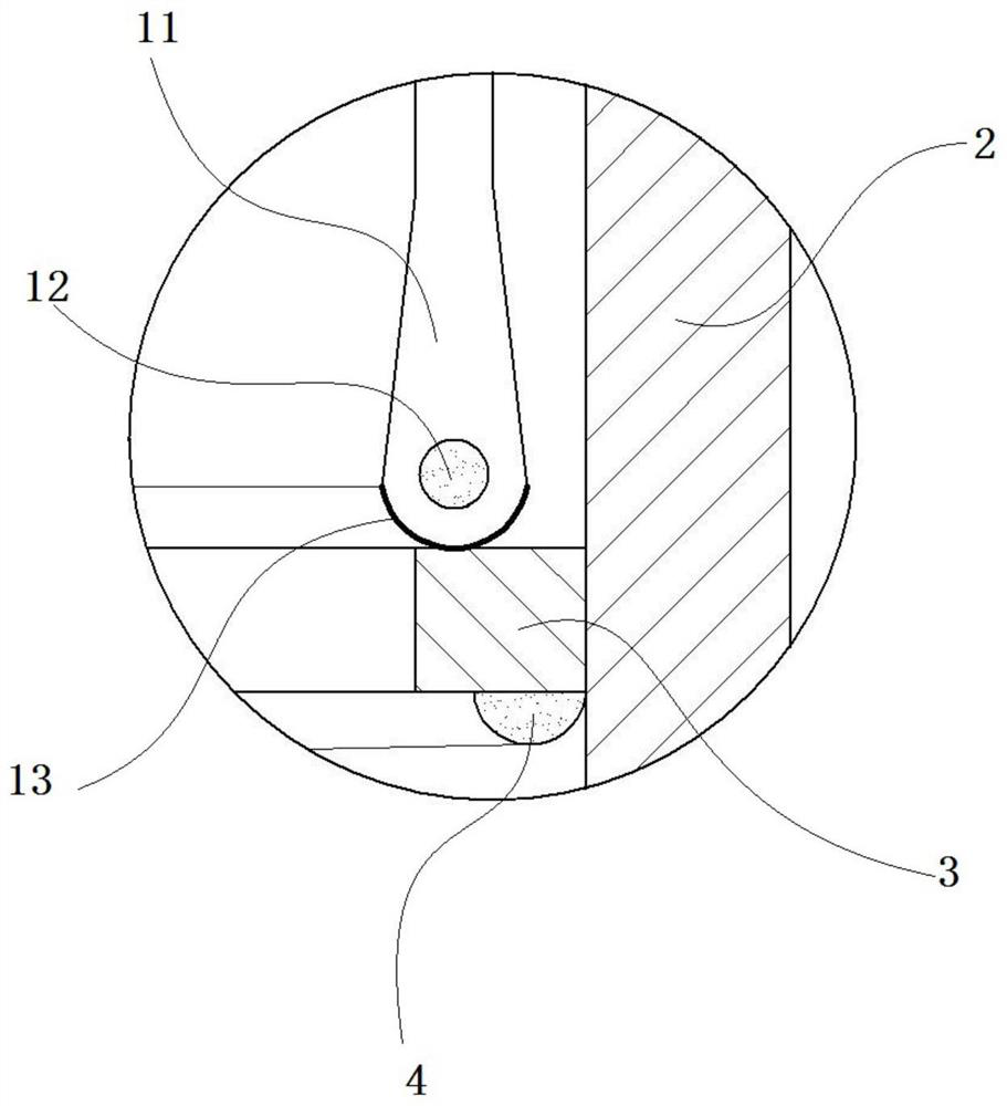
[0032] combine Figure 4 As shown, the locking cylinder 1 includes an upper cylinder section 10 and a lower expansion section 11. The inner diameter of the cylinder section 10 is consistent, the inner diameter of the expansion section 11 is smaller at the bottom and larger at the top, and the outer diameter of the expansion section 11 is larger at the bottom and thicker at the top. ...


PUM


Abstract

The invention belongs to the technical field of purifiers and provides a filter element positioning cylinder. The present invention includes a cylinder and a locking cylinder, the cylinder is vertically connected, the upper port of the cylinder is provided with a stepped hole, and the bottom side wall of the stepped hole is surrounded by a limiting groove; the locking cylinder includes For the upper cylindrical section and the lower expansion section, the inner diameter of the cylindrical section is consistent, the inner diameter of the expansion section is smaller at the bottom and larger at the top, and the side wall thickness of the expansion section is thicker at the bottom and thinner at the top; the cylinder section The inner sleeve is placed in the stepped hole, and the expansion section is located in the limiting groove, so that the technical effect of simple, fast and stable locking of the filter element purification unit can be achieved.

Description

technical field [0001] The invention relates to the technical field of purifiers, in particular to a filter element positioning cylinder. Background technique [0002] The patent document with the notification number CN206467094U discloses a filter element layout waterway structure. The scheme recorded in this document mainly adopts the filter element water purification unit distributed in an array of 3 lining brackets for the filter element, and the filter element purification unit is cylindrical. , The filter element water purification unit is positioned and locked through the inner lining shell. The inner lining shell is integrally formed. The fixing tightness between the inner lining shell and the filter element purification unit is not firm, and it is easy to loosen during use. . Contents of the invention [0003] Aiming at the defects in the prior art, the present invention provides a filter element positioning cylinder, which realizes the technical effect of simply...

Claims


Application Information

Patent Timeline
Patent Type & Authority Patents(China)
IPC IPC(8): B01D35/30
CPCB01D35/301
Inventor 吴联星吴锦华
Owner 吴联星
Why Eureka
Try Eureka