Collar clamp apparatus

a clamping device and clamping technology, applied in the field of collapsing devices, can solve the problems of unattractive, difficult to adjust, and difficult to meet the needs of patients, and achieve the effects of affecting blood flow and circulation, complex and unattractive braces and joint support accessories

Inactive Publication Date: 2008-02-14
NORDT DEVMENT
View PDF9 Cites 37 Cited by
  • Summary
  • Abstract
  • Description
  • Claims
  • Application Information

AI Technical Summary

Problems solved by technology

However, most available braces and joint-support accessories are complex, unattractive, and uncomfortable There are braces for preventing joint motion or for maintaining a particular joint position.
Typical such braces, having hard-shell or rigid beam components, are not typically conveniently adjusted with regard to forces and resulting pressures applied to an arm or leg and with regard to a comfortable fit.
These braces generally include binding arrangements that tend to apply circumferential forces to an arm or leg and adversely affect blood flow and circulation.

Method used


Image

  • Collar clamp apparatus
  • Collar clamp apparatus
  • Collar clamp apparatus

Examples


first embodiment

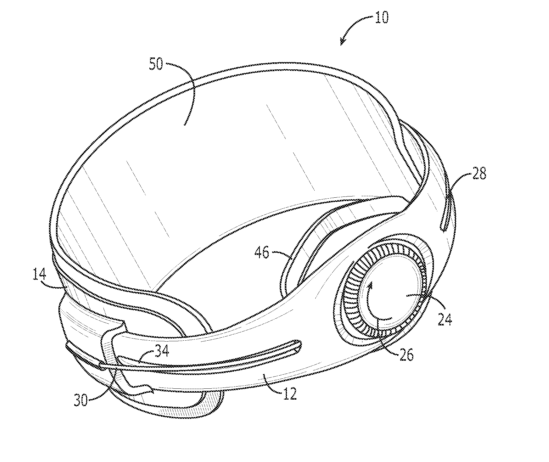
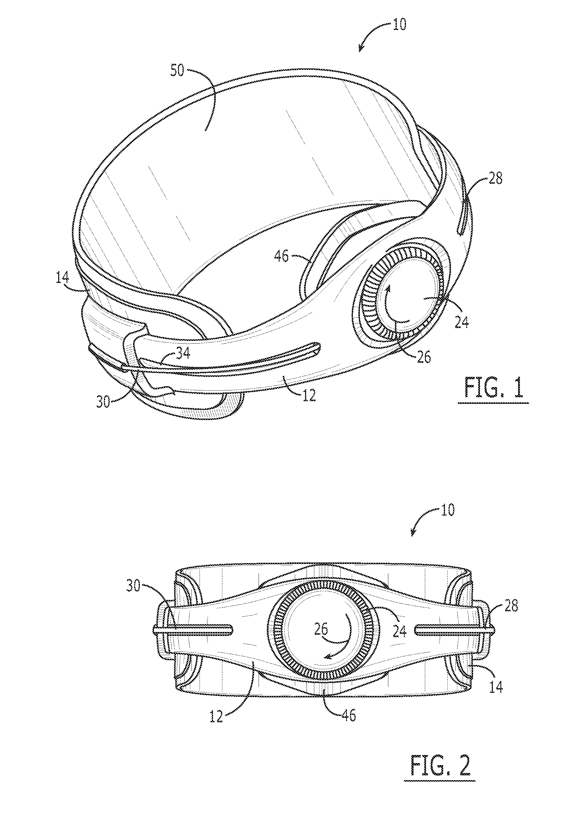
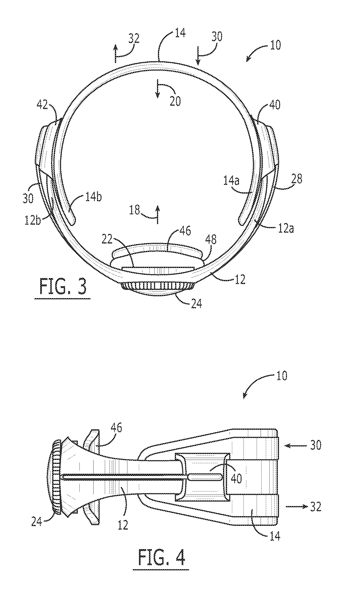
[0037] Furthermore, by pressing of the rotatable control knob 24, the directionally opposing forces 18, 20 applied to an appendage are decreased or are entirely terminated. Thus, in the invention, the apparatus 10 closes upon rotation of the rotatable control knob and tends to spring back open upon pressing of the control knob. The apparatus 10 closes in that the second partial collar 14 moves relative to the first partial collar 12 in a first direction 30, thereby, increasing the forces 18, 20 (FIG. 3) when the apparatus is clamped in engagement with an appendage. The apparatus opens in that the second partial collar 14 moves relative to the first partial collar 12 in a second direction 32, thereby decreasing the forces 18, 20 when the apparatus is tightly clamped in engagement with an appendage.

[0038] In another embodiment of the invention, not illustrated, a coapting shell encircling an appendage closes upon rotation of a rotatable control knob in one rotational direction and ope...

second embodiment

[0050] Turning now to a second embodiment shown in various views in FIGS. 6-10, an apparatus 110 for circumferential disposition on an appendage such as an arm or leg comprises a first partial collar 112, a second partial collar 114, and a tensioning system 116 (FIG. 10). The first partial collar 112 and second partial collar 114 are each adapted for partially encircling an appendage such that together they completely encircle an appendage when the apparatus 110 is disposed on the appendage. For example, in FIG. 11 the apparatus 110 is disposed on an arm proximal a shoulder. In this disposition, the apparatus 110 is nominally referred to as a shoulder brace.

[0051] The tensioning system 116 (FIG. 10) draws together the first partial collar 112 and second partial collar 114. When the apparatus 110 is disposed on an appendage as shown in FIG. 11, the first partial collar 112 and second partial collar 114 are drawn together by the tensioning system 116 (FIG. 10). Respective forces are t...


PUM


Abstract

An apparatus for disposition on appendage, such as an arm or leg, is capable of encircling and applying opposing forces selectively thereto. A C-shaped component receives one side of the appendage, a second C-shaped component receives the other side of the appendage, and a tensioning system draws the two components together for selective application of pressure to the appendage. Outriggers and pressure applicators may be used to apply pressure to extended areas of the appendage that otherwise would not be engaged by the C-shaped components. Side-to-side tissue compression thereby is provided for deflection of muscle forces, functional shortening of muscle length, and the maintenance of neurovascular channels. Circumferential forces may be minimized based on semirigid characteristics of the components. Elbow and shoulder braces apply side-to-side tissue compression to arms.

Description

CROSS-REFERENCE TO RELATED APPLICATIONS [0001] The present application is a continuation of, and claims the benefit of priority under 35 U.S.C. §120 to, U.S. patent application Ser. No. 11 / 187,590, pending, which '590 application published as US 2006 / 0020237 and which '590 application is a continuation-in-part patent application of each of U.S. design patent application Ser. No. 29 / 209,971, filed Jul. 22, 2004, now U.S. design Pat. No. 519,637, and U.S. design patent application Ser. No. 29 / 209,987, filed Jul. 22, 2004, now U.S. design Pat. No. 521,644, and which '590 application is a nonprovisional patent application of, and claims the benefit of priority under 35 U.S.C. §119(e) to, each of U.S. provisional patent application Ser. No. 60 / 590,940, filed Jul. 22, 2004, expired, and U.S. provisional patent application Ser. No. 60 / 590,947, filed Jul. 22, 2004, expired. Each of these patent applications, patents, and patent application publication is incorporated herein by reference.COP...

Claims


Application Information

Patent Timeline
Patent Type & Authority Applications(United States)
IPC IPC(8): A61F13/00
CPCA61F5/32A61F5/0118
Inventor NORDT, WILLIAM E. IIIKOVACEVICH, IAN D.DAHLQUIST, KEVIN J.PHILPOTT, TOM J.
Owner NORDT DEVMENT
Why Eureka
Try Eureka