Method and apparatus for applying energy to biological tissue including the use of tumescent tissue compression
What is AI technical title?
AI technical title is built by Patsnap AI team. It summarizes the technical point description of the patent document.
a technology of biological tissue and energy, applied in the field of method and apparatus for applying energy to shrink hollow anatomical structure, can solve problems such as long occlusion, and achieve the effect of preventing coagulum formation and further enhancing the ligation
Inactive Publication Date: 2008-02-14
GOLDMAN MITCHEL P +3
View PDF0 Cites 14 Cited by
Summary
Abstract
Description
Claims
Application Information
AI Technical Summary
This helps you quickly interpret patents by identifying the three key elements:
Problems solved by technology
Method used
Benefits of technology
Benefits of technology
[0025] Alternate means to prevent coagulum formation include fluid displacement of blood at the treatment site, or exsanguination by inducing self-constriction of the vessel. In the latter, self-constriction includes, but is not limited to, intraluminal delivery of a vasoconstrictive drug. Self-constriction also aids in pre-shaping the vein for ligation, as discussed previously. If the fluid delivered to the site is a sclerosant, the ligation effects would be further enhanced.
Problems solved by technology
The electrode is then moved along a site within the selected length while continuously applying energy to result in a lengthy occlusion.
Method used
Image
Click on the blue label to locate the original text in one second.
Reading with bidirectional positioning of images and text.
Examples
Embodiment Construction
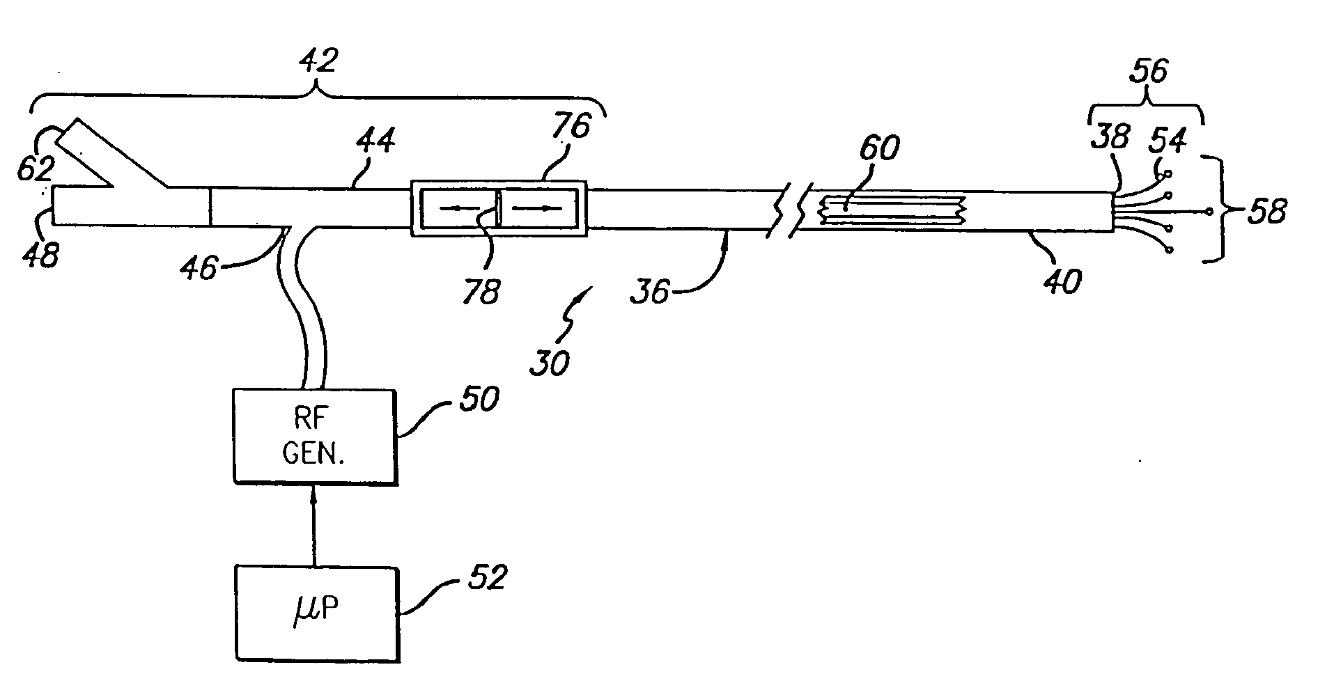
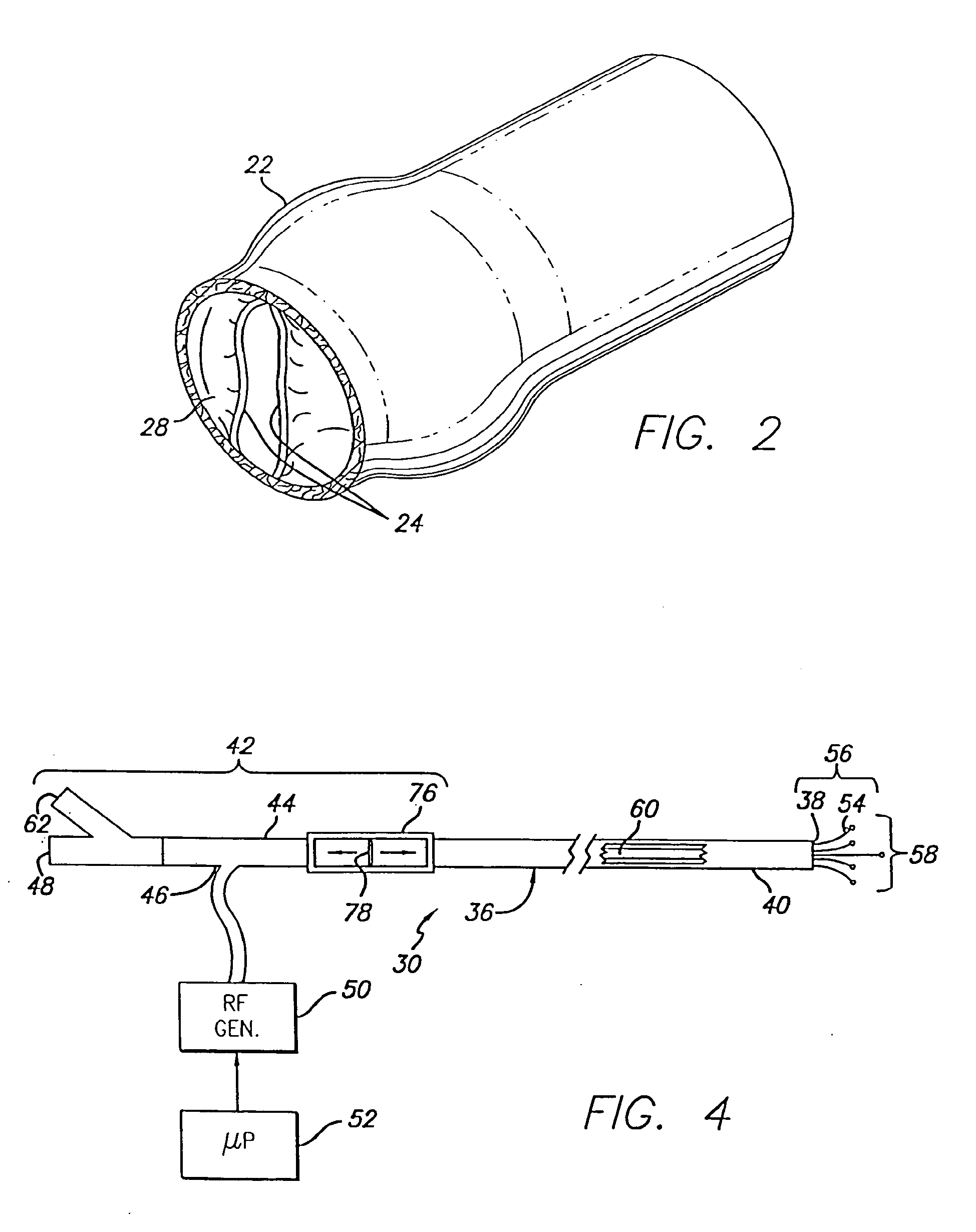
[0044] As shown in the exemplary drawings, the invention is directed toward the intravenous treatment of veins using a catheter to deliver at least one electrode to a venous treatment site. As used herein, like reference numerals will designate similar elements in the various embodiments of the present invention to be discussed. In addition, unless otherwise noted, the term “working end” will refer to the direction toward the treatment site in the patient, and the term “connecting end” will refer to the direction away from the treatment site in the patient. The invention will be described in relation to the treatment of the venous system of the lower limbs. It is to be understood, however, that the invention is not limited thereto and may be employed intraluminally to treat veins in other areas of the body such as hemorrhoids, esophageal varices, and venous-drainage-impotence of the penis. Furthermore, although the invention will be described as using RF energy from the electrode, i...
PUM
Property
Measurement
Unit
diameter
aaaaa
aaaaa
diameter
aaaaa
aaaaa
length
aaaaa
aaaaa
Abstract
An electrode catheter is introduced into a hollow anatomical structure, such as a vein, and is positioned at a treatment site within the structure. Tumescent fluid is injected into the tissue surrounding the treatment site to produce tumescence of the surrounding tissue which then compresses the vein. The solution may include an anesthetic, and may further include a vasoconstrictive drug that shrinks blood vessels. The tumescent swelling in the surrounding tissue causes the hollow anatomical structure to become compressed, thereby exsanguinating the treatment site. Energy is applied by an electrode catheter in apposition with the vein wall to create a heating effect. The heating effect causes the hollow anatomical structure to become molded and durably assume the compressed dimensions caused by the tumescent technique. The electrode catheter can be moved within the structure so as to apply energy to a large section of the hollow anatomic structure. In a further aspect, the location of the electrodes is determined by impedance monitoring. Also, temperature sensors at the treatment site are averaged to determine the site temperature.
Description
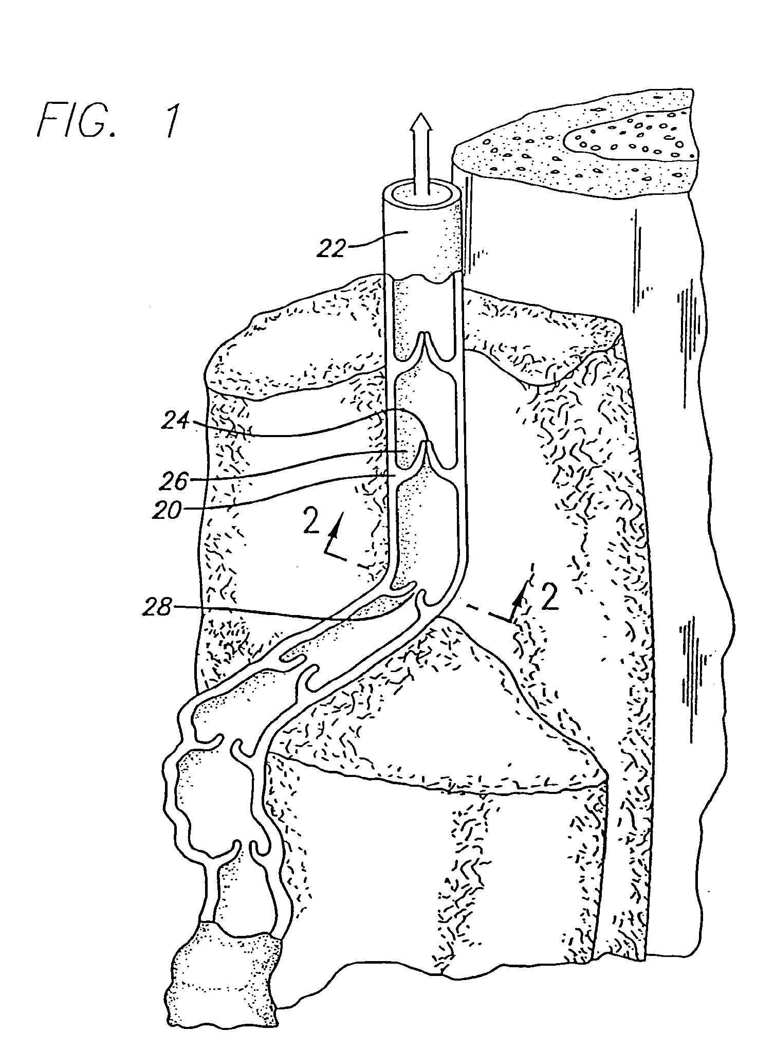
[0001] This application is a continuation of Ser. No. 10 / 872,646, filed Jun. 21, 2004, which is a continuation of Ser. No. 09 / 899,885 (now U.S. Pat. No. 6,752,803), filed Jul. 6, 2001, which is a continuation of Ser. No. 09 / 267,127 (now U.S. Pat. No. 6,258,084), filed Mar. 10, 1999, which is a continuation-in-part of Ser. No. 09 / 138,472 (now U.S. Pat. No. 6,179,832), filed Aug. 21, 1998, which is a continuation-in-part of Ser. No. 08 / 927,251 (now U.S. Pat. No. 6,200,312), filed Sep. 11, 1997.BACKGROUND [0002] The invention relates generally to a method and apparatus for applying energy to shrink a hollow anatomical structure, such as a fallopian tube or a vein, including but not limited to, superficial and perforator veins, hemorrhoids, and esophageal varices. In some particular aspects, the invention relates to a method for compressing an anatomical structure prior to the application of energy and apparatus including an electrode device having multiple leads for applying energy to ...
Claims
Application Information
Patent Timeline
Application Date:The date an application was filed.
Publication Date:The date a patent or application was officially published.
First Publication Date:The earliest publication date of a patent with the same application number.
Issue Date:Publication date of the patent grant document.
PCT Entry Date:The Entry date of PCT National Phase.
Estimated Expiry Date:The statutory expiry date of a patent right according to the Patent Law, and it is the longest term of protection that the patent right can achieve without the termination of the patent right due to other reasons(Term extension factor has been taken into account ).
Invalid Date:Actual expiry date is based on effective date or publication date of legal transaction data of invalid patent.
Patent Type & AuthorityApplications(United States)

