
System and method for compressor capacity modulation in a heat pump

Inactive Publication Date: 2008-02-21
BRISTOL COMPRESSORS INT
View PDF6 Cites 36 Cited by
  • Summary
  • Abstract
  • Description
  • Claims
  • Application Information

AI Technical Summary

Benefits of technology

[0008]One advantage of the present invention is increased system performance, efficiency and capacity control at reduced outdoor ambient temperatures in both heating and cooling modes of operation.
[0009]A further advantage of the present invention is that the capacity modulation of the compressor is invisible when compared to a standard single stage compressor.
[0010]Another advantage of the present invention is that the motor drive can be used for different types of input power (i.e., multi-voltage and single phase or three phase) and with different types of compressors and motors.
[0011]An additional advantage of the present invention is that no additional starting components are needed, e.g., start capacitors and / or relays.
[0012]Another advantage of the present invention is that the compressor output can be tuned to a specific system incorporating the compressor.

Problems solved by technology

The use of line voltages and frequencies results in the motor being limited to one operating speed that is based on the input frequency to the motor.
The operation of the motor at one speed, in turn, results in the compressor being limited to a single output capacity.
Furthermore, motors that require their own controller or electronic drive, e.g., switched reluctance motors, cannot be used for these HVAC systems, as such motors cannot operate directly from standard (main) voltages and frequencies.
One problem with the compressor being limited to a single output capacity is that the compressor, especially a reciprocating compressor, has a limited heating capacity at reduced outdoor ambient temperatures.
This limited heating capacity produced by the compressor adversely affects the EER (Energy Efficiency Rating) and HSPF (Heating Season Performance Factor) of any system incorporating the compressor during testing and in subsequent operation of the system.
Furthermore, the limited heating capacity output of the compressor at reduced outdoor ambient temperatures requires additional (and more costly) heating techniques to be used to maintain a setpoint temperature in an enclosed space.

Method used


Image

  • System and method for compressor capacity modulation in a heat pump
  • System and method for compressor capacity modulation in a heat pump
  • System and method for compressor capacity modulation in a heat pump

Examples


Embodiment Construction

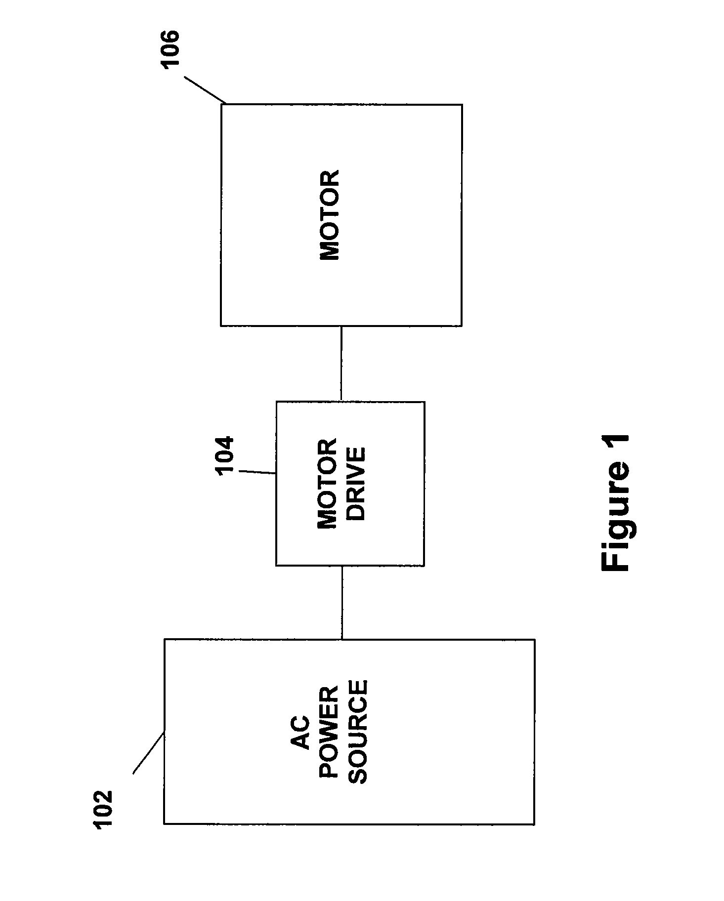
[0022]FIG. 1 illustrates generally a system configuration of the present invention. An AC power source 102 supplies electrical power to a motor drive 104, which powers a motor 106. The motor 106 is preferably used to drive a corresponding compressor of a HVAC&R system (see generally, FIGS. 3A and 3B). The AC power source 102 provides single phase or multi-phase (e.g., three phase), fixed voltage, and fixed frequency AC power to the motor drive 104. The motor drive 104 can accommodate virtually any AC power source 102, preferably an AC power source 102 that can supply an AC voltage or line voltage of 187 V, 208 V, 230 V, 380 V, 460 V, or 600 V, at a line frequency of 50 Hz or 60 Hz.

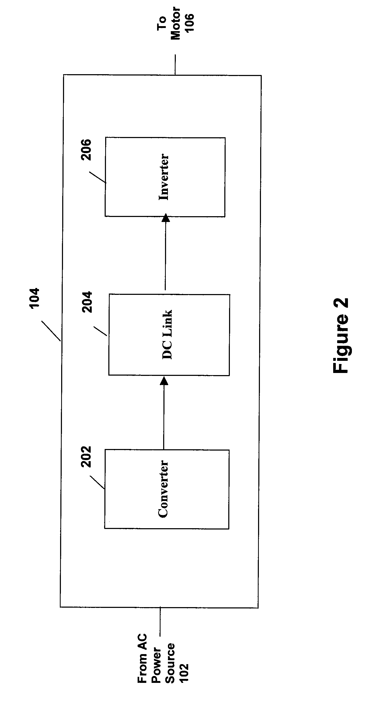
[0023]The motor drive 104 can be a variable speed drive (VSD) or variable frequency drive (VFD) that receives AC power having a particular fixed line voltage and fixed line frequency from the AC power source 102 and provides power to the motor 106 at a desired voltage and desired frequency (including provi...


PUM


Abstract

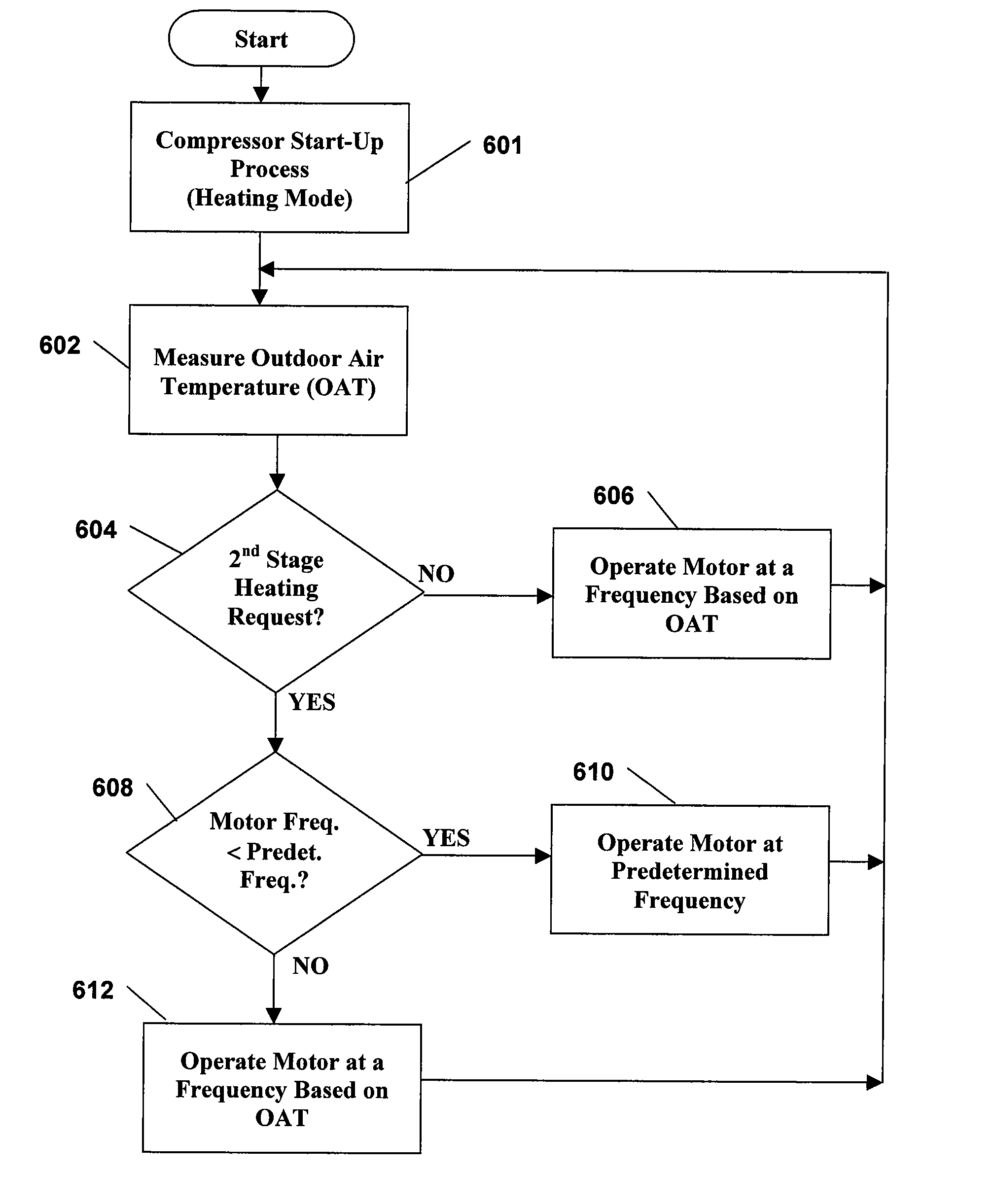
A system and method is provided to control and operate a compressor to have two or more discrete output capacities in response to an outdoor temperature measurement. During operation of the compressor in an air conditioning or cooling mode, the compressor has a first output capacity in response to the outdoor temperature being greater than a first temperature setpoint and the compressor has a second output capacity in response to the outdoor temperature being less than a second temperature setpoint. During operation of the compressor in a heating mode, the compressor has different output capacities based on the outdoor ambient temperature.

Description

BACKGROUND OF THE INVENTION[0001]The present invention relates generally to a control system for a compressor. More specifically, the present invention relates to a capacity modulation system for a compressor that can automatically adjust the capacity of the compressor in a heat pump during a heating operation.[0002]Frequently, motors for driving compressors in heating, ventilation and air conditioning (HVAC) systems are designed to operate from standard line (main) voltages and frequencies (e.g., 230 V, 60 Hz) that are available at the location where the HVAC system is being operated. The use of line voltages and frequencies results in the motor being limited to one operating speed that is based on the input frequency to the motor. The operation of the motor at one speed, in turn, results in the compressor being limited to a single output capacity. Furthermore, motors that require their own controller or electronic drive, e.g., switched reluctance motors, cannot be used for these H...

Claims


Application Information

Patent Timeline
IPC IPC(8): F25B49/00
CPCF25B49/025F25B2600/021Y02B30/741F25B2700/2106F25B2600/024Y02B30/70
Inventor TOLBERT, JOHN WILLARD
Owner BRISTOL COMPRESSORS INT
Learn More