Walking cane assembly

a walking cane and assembly technology, applied in the field of collapsible walking cane assembly, can solve the problems of reducing his/her stability, and achieve the effect of quick and easy adjustment and readily adaptability

Inactive Publication Date: 2008-02-21
WILLIS PHILLIP MINYARD
View PDF99 Cites 39 Cited by
  • Summary
  • Abstract
  • Description
  • Claims
  • Application Information

AI Technical Summary

Benefits of technology

[0012] The present invention is directed to a walking cane assembly having the structural versatility to be selectively disposed between a collapsed or folded position and an operative position. Moreover, the various structural components of the various preferred embodiments of the cane assembly of the present invention are cooperatively structured and disposed to allow a certain degree of adjustability of the cane assembly. Such adjustable features include, but are not limited to, a variance in the length of the cane assembly and a selective positioning of a hand grip of the handle assembly in any of a plurality of angular orientations relative to the length or longitudinal access of the shaft. As such, the walking cane assembly of the present invention can be quickly and easily adjusted to accommodate users of different sizes, while also being readily adaptable to accommodate the personal preferences or physical demands of a user.
[0015] As set forth above, cooperatively disposed components of the cane assembly are cooperatively structured to provide for selective adjustment of both the length of the shaft and the specific angular orientation of a handle assembly. The handle assembly includes a hand grip and an elongated mounting portion which serves to removably connect the grip to the proximal end of the shaft. The connection between the handle assembly and the shaft is such as to allow the mounting assembly and the attached grip to be adjusted along the length of the shaft adjacent to the proximal end. In addition, the grip is removably secured to the outer most end of the mounting portion of the handle assembly and is preferably attached thereto by a mating, threaded connection. As such, the grip maybe rotated relative to the mounting portion as well as the shaft, when the mounting portion and the shaft are fixedly, but removably secured to one another. This rotational movement facilitates a minor adjustment in the operative length of the cane assembly by allowing the grip to rotate towards or away from the outer most end of the mounting portion.
[0016] However the rotational, threaded interconnection between the grip and the mounting portion may be considered even more significant by allowing the grip to be selectively disposed in any one of a plurality of angular orientations relative to the axis of the mounting portion, as well as the shaft to which it is removably but fixedly attached. One benefit of varying the angular orientation between the grip and the mounting portion is the ability to position or orient a connection assembly, serving to interconnect the handle assembly and the shaft, at various, less noticeable locations relative to the grip. Personal preferences of a user may thereby be accommodated.
[0018] Therefore, the cane assembly of the present invention overcomes recognized disadvantages and problems associated with cane type mobility aides conventionally known and commonly used by the elderly and / or physically challenged individuals. Included in the various operative and structural features of the preferred embodiments of the subject cane assembly is the ability to selectively adjust its physical characteristics to accommodate the size as well as other requirements of a user. In addition, the cane assembly is capable of being selectively disposed in either an operative position, when intended for use, or a collapsed position, so as to assume a smaller volume for storage and / or transport. In addition, while the cane assembly of the present invention comprises a lightweight construction the cooperative nature of the various components of the cane assembly provide reliable stability as well as firm engagement with the surface over which the user of the cane assembly is traveling.

Problems solved by technology

When present, such wheel or equivalent structures increase the mobility of a user, but may possibly reduce his / her stability, especially when all of the legs of a given walker frame include a wheel or roller structure connected thereto.
However, the providing of such stability should not detract from the preferred lightweight structure of a proposed walking cane assembly.

Method used


Image

  • Walking cane assembly
  • Walking cane assembly
  • Walking cane assembly

Examples


Embodiment Construction

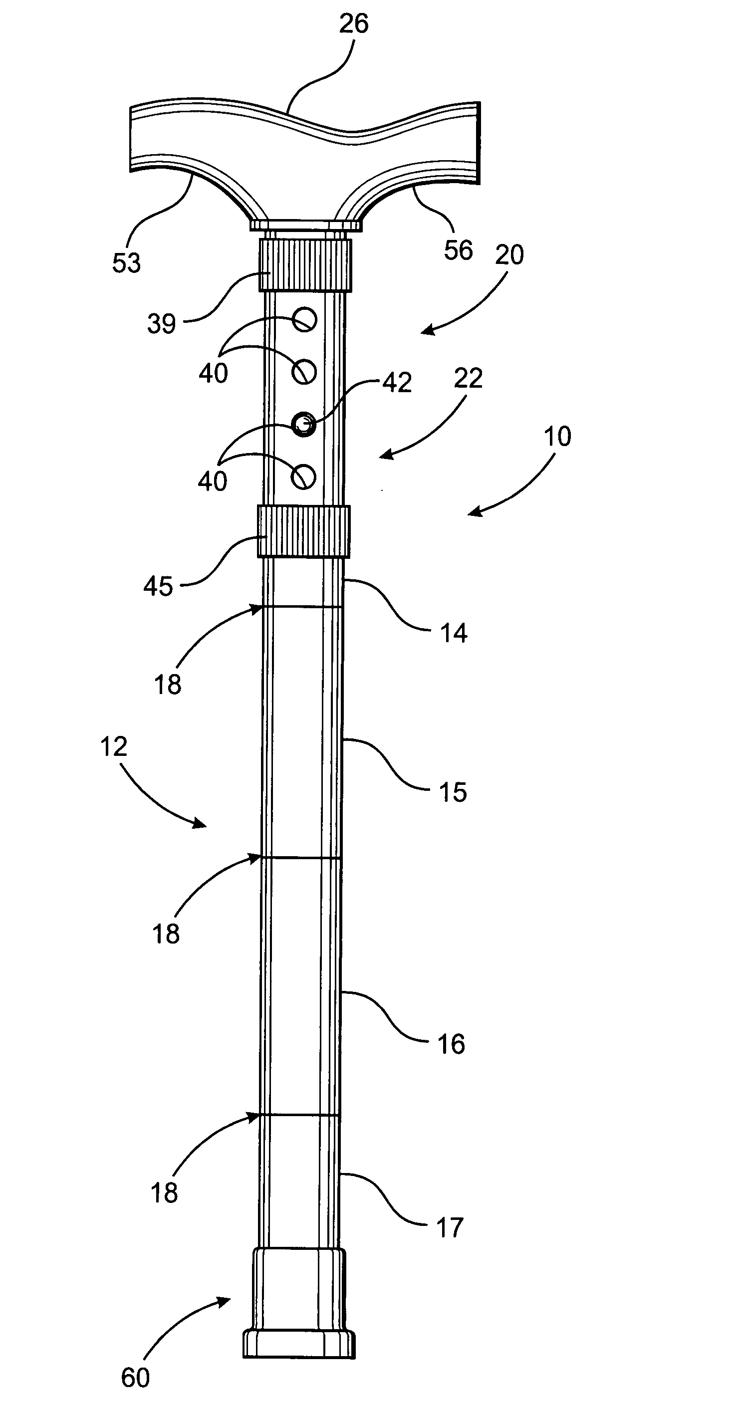
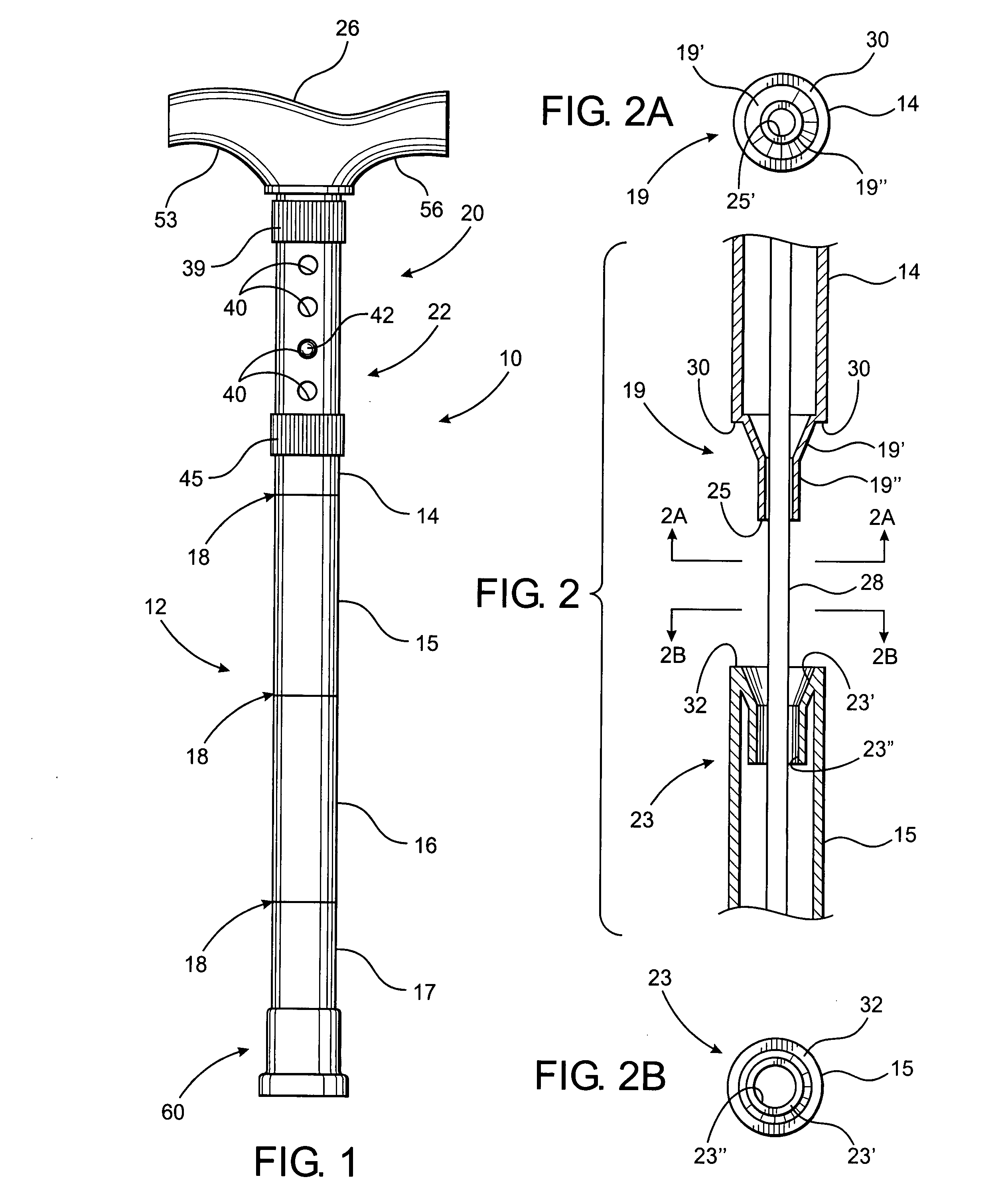
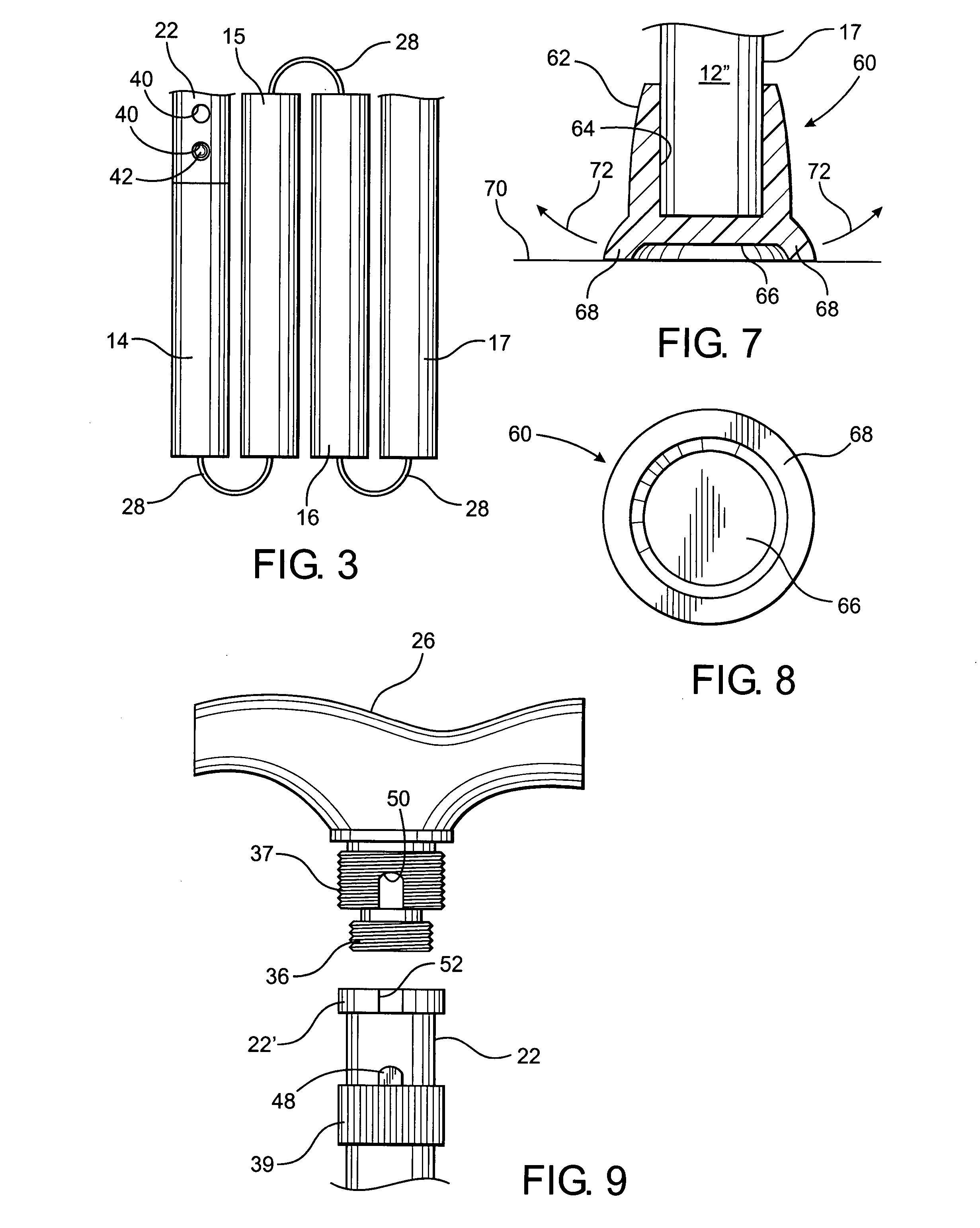
[0035] As shown in the accompany drawings, the present invention is directed to a walking cane assembly generally indicated as 10 and comprising a shaft generally indicated as 12 which is represented in FIG. 1 in its operative position. When so positioned, the shaft 12, comprises a plurality of elongated sections 14, 15, 16, 17, etc. disposed into a coaxial orientation. The specific number of the elongated sections 14 through 17 may vary. However, there should be at least two of such sections to facilitate disposition of the cane assembly 10 in the collapsed position of FIG. 3. By way of example only the preferred embodiment of FIG. 1, comprises four elongated sections. As described in greater detail hereinafter, the primary reference to FIGS. 2, 2a and 2b, adjacent ones of the plurality of elongated sections 14 through 17 are interconnected by a joint assembly 18 which facilitates the selective disposition of the sections 14 through 17 in either the operative position of FIG. 1 or ...


PUM


Abstract

A walking cane assembly including an elongated shaft having separable segments connected by joint assemblies, wherein the shaft is disposable between a collapsed position, and a elongated, substantially linear, operative position. A stabilizing assembly is operatively structured with one or more of the joint assemblies so as to facilitate stabilization of the shaft in the operative position. A handle assembly is adjustably connected to a proximal end of the shaft and is structured to facilitate selective adjustment thereof both axially and rotationally relative to the length of the shaft thereby allowing adjustment in the operative length of the walking cane as well as the angular orientation of the grip relative to the shaft. And end member is connected to the distal end of the shaft and is structured to provide a firm, non-slipping engagement with a supporting surface of a user of the cane assembly.

Description

CLAIM OF PRIORITY [0001] The present application is a continuation patent application of previously filed, now pending application having Ser. No. ______, filed on May 30, 2007, which is a continuation-in-part application of previously filed, pending application having Ser. No. 11 / 206,674, filed on Aug. 18, 2005, which is a continuation-in-part application of previously filed, now pending application having Ser. No. 11 / 129,565, filed on May 13, 2005, incorporated herein by reference.BACKGROUND OF THE INVENTION [0002] 1. Field of the Invention [0003] This invention is directed to a collapsible walking cane assembly selectively disposable between an operative position and a collapsed position and having an adjustable length. The angular orientation of a hand grip relative to a remainder of the cane assembly may also be varied and a stabilizing assembly is provided to facilitate stability of the shaft when in the operative position. [0004] 2. Description of the Related Art [0005] Many ...

Claims


Application Information

Patent Timeline
Patent Type & Authority Applications(United States)
IPC IPC(8): A45B9/00
CPCA45B3/12A45B9/04A45B9/02
Inventor WILLIS, PHILLIP MINYARD
Owner WILLIS PHILLIP MINYARD
Why Eureka
Try Eureka