Container

a container and storage technology, applied in the field of containers, can solve the problems of occupying a great deal of space in unused containers, difficult to find a matching base and cover in a disorganized drawer, and still be difficult to match a base with a cover

Inactive Publication Date: 2008-02-21
TUCKER EDWARD B +7
View PDF22 Cites 28 Cited by
  • Summary
  • Abstract
  • Description
  • Claims
  • Application Information

AI Technical Summary

Benefits of technology

[0006] In view of the foregoing, the present invention provides containers whose covers can be stacked together in two different ways. First, the covers can be stacked into an “aligned” stack. The aligned stack provides enough structural rigidity for bulk handling during manufacturing. Second, the covers can be stacked into a “locked” stack. The locked stack provides even more structural rigidity than does the aligned stack and is useful when storing unused covers.
[0008] The covers and bases can be economically constructed from relatively thin-gauge plastic so that the user can either wash them after use or dispose of them with the view that their purchase price allows them to be used as a consumable good. The container can be readily manufactured, for example, with conventional thermoforming equipment. The cover can be made from a semi-transparent material to ensure satisfactory visibility of the container's contents. The container can be suitable for refrigerator, freezer, microwave, and machine dishwasher use.

Problems solved by technology

When not in use, the containers are often stored haphazardly into drawers.
In this case, the unused containers take up a great deal of room, and finding a matching base and cover in a disarranged drawer may be difficult.
While the bases of the containers usually nest and therefore take up less room than in a disorganized drawer, it may still be difficult to match a base with a cover.
In addition, the covers may not stack and the covers may tend to topple down.
These stacks may be precarious, and their fall may cause food to spill from the containers.

Method used


Image

  • Container
  • Container
  • Container

Examples


Embodiment Construction

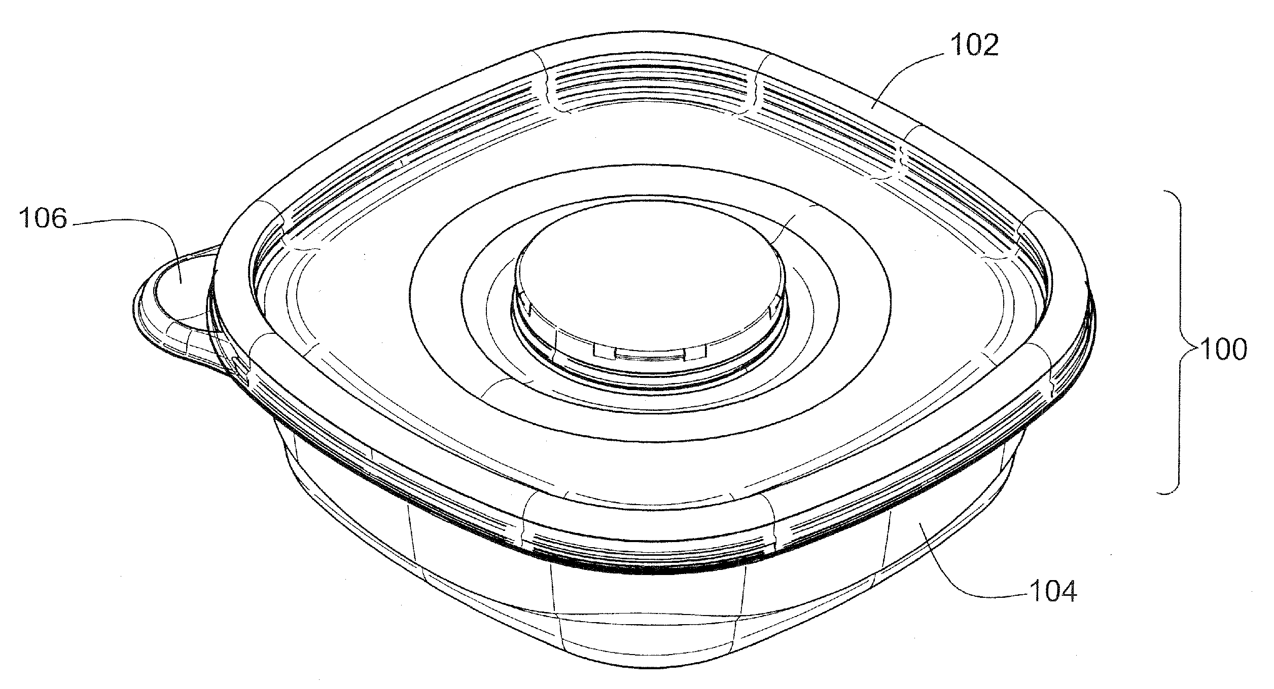
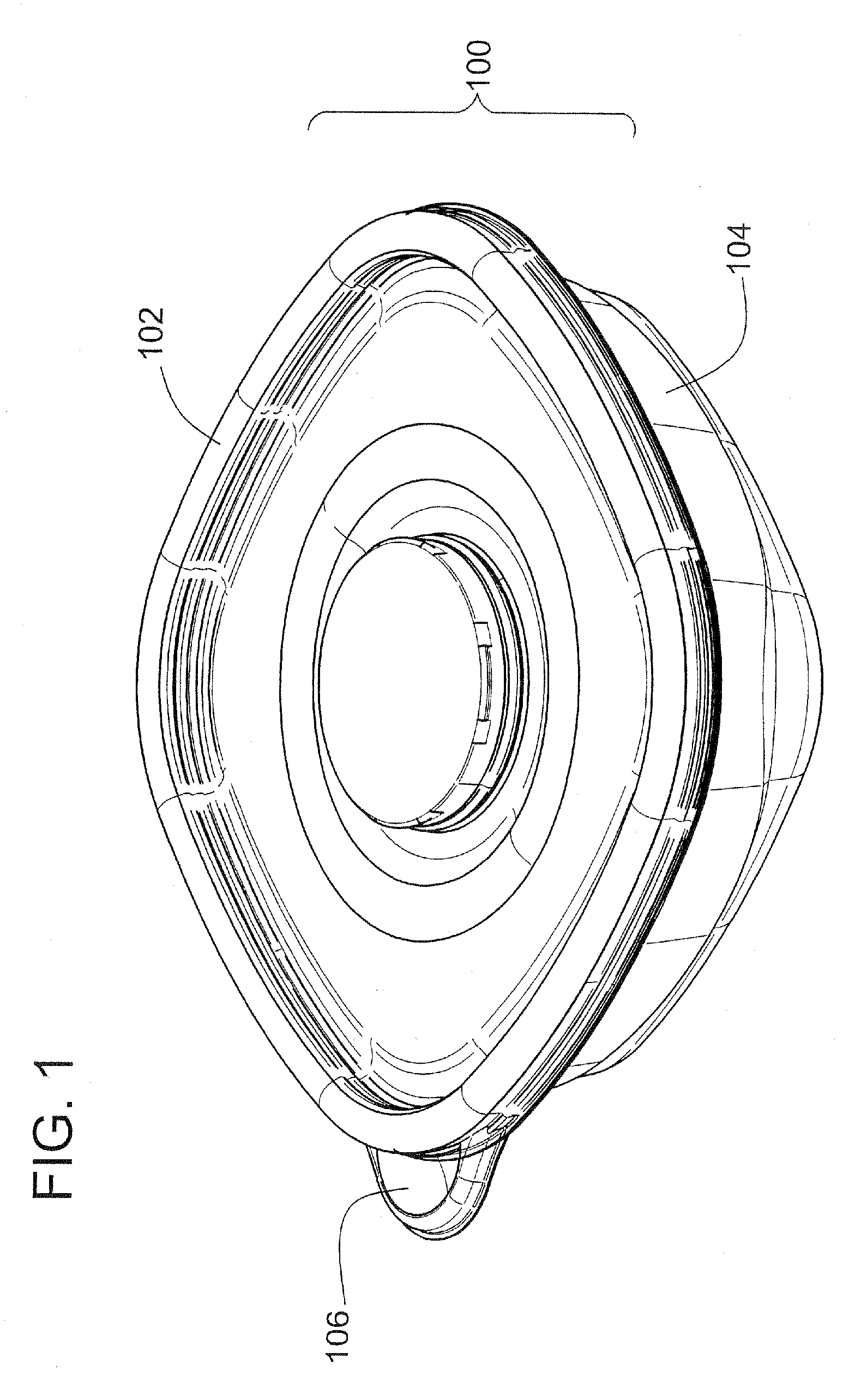
[0033] Turning to the drawings, wherein like reference numerals refer to like elements, a first embodiment of the present invention is illustrated in FIGS. 1 through 5. A container 100 includes a flexible cover 102 sealingly engaged to a base 104. In the example of FIGS. 1 through 5, the container 100 is depicted as substantially square with rounded corners. In other embodiments of the present invention, the container 100 has other shapes such as rectangular, circular, or elliptical.

[0034] The container cover 102 can include at least one gripping tab 106 to facilitate removal of the cover 102 from the container base 104. In some embodiments, the gripping tab 106 includes one or more cross-ribs or a textured surface to improve a user's grip on the tab 106.

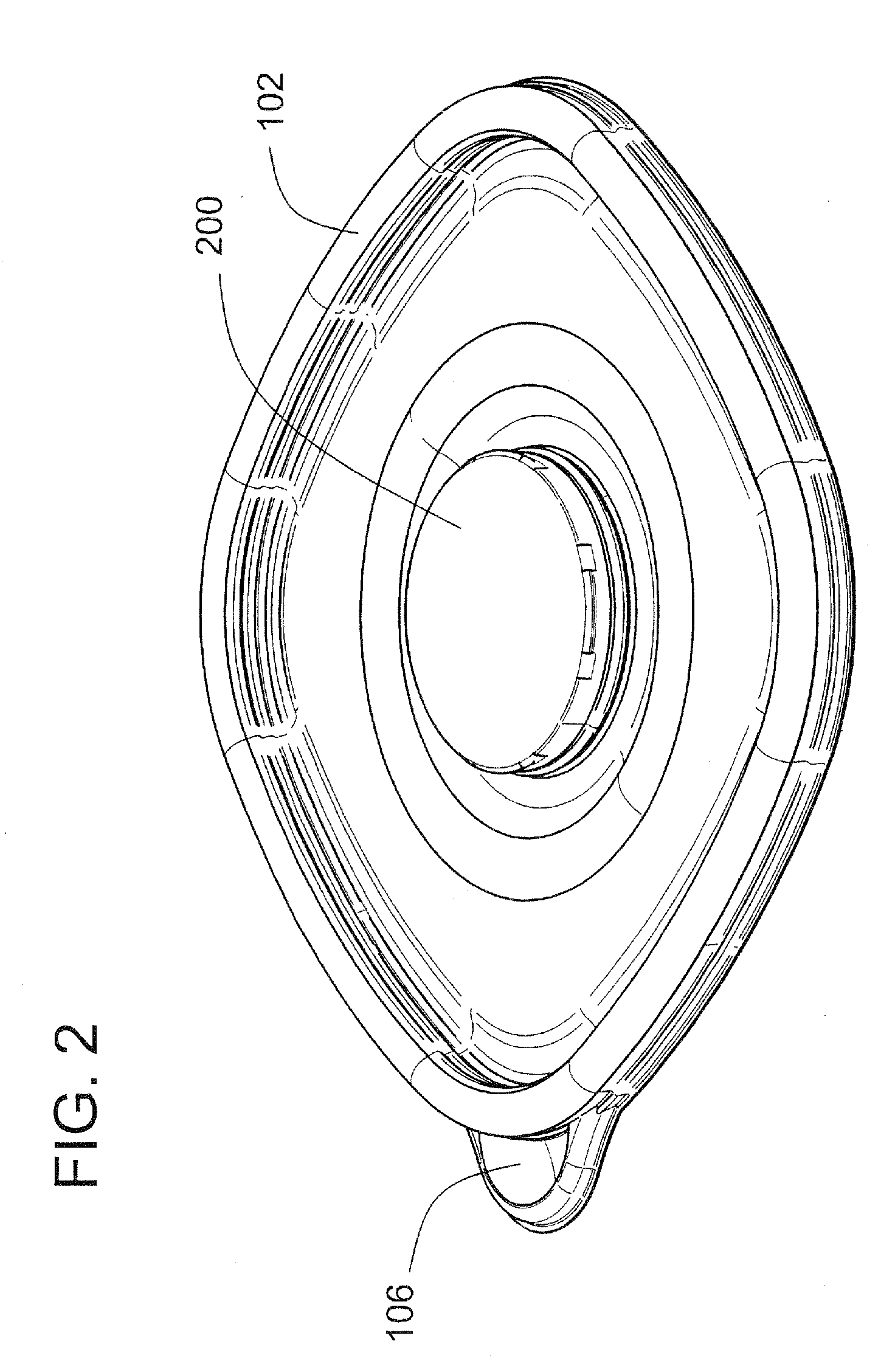
[0035] The container cover 102 illustrated in FIGS. 2 and 3 includes an engagement portion 200 that allows the cover 102 to engage with the engagement portion 200 of a second cover 102 to form a locked stack of covers 102. This lo...


PUM


Abstract

The container covers stack together in two different ways. First, the covers can be stacked into an “aligned” stack. The aligned stack provides structural rigidity for bulk handling during manufacturing. Second, the covers can be stacked into a “locked” stack. The locked stack provides even more structural rigidity than does the aligned stack and is useful when storing unused covers. The container cover includes a first closure portion, an engagement portion, and an alignment portion. The base includes a second closure portion. The first closure portion of the cover is sealingly engageable with the second closure portion of the base to define a sealed storage area. The alignment portion of the cover is engageable with the alignment portion of a second cover to form an aligned cover stack. The engagement portion of the cover is engageable with the engagement portion of a second cover to form a locked cover stack.

Description

[0001] This application is a continuation of U.S. application Ser. No. 11 / 559,527, filed Nov. 14, 2006, which is a continuation in part of International Application No, PCT / US 06 / 06263, filed Feb. 22, 2006, which claims benefit of U.S. Provisional Application No. 60 / 655,830, filed Feb. 23, 2005.FIELD OF THE INVENTION [0002] The present invention relates generally to containers, and, more particularly, to containers whose covers align together when stacked in a first position and which can be locked together in a second position. BACKGROUND OF THE INVENTION [0003] Rigid, thermoplastic food containers are generally known. Users often accumulate a large number of these containers in different sizes and shapes. When not in use, the containers are often stored haphazardly into drawers. In this case, the unused containers take up a great deal of room, and finding a matching base and cover in a disarranged drawer may be difficult. To avoid this, some users stack the containers in cabinets....

Claims


Application Information

Patent Timeline
Patent Type & Authority Applications(United States)
IPC IPC(8): B65D51/00
CPCB65D21/0219B65D2543/00027B65D21/0223B65D21/0222
Inventor TUCKER, EDWARD B.RAMANUJAM, ANANDRACANA, LAWERENCE JOHNMARASLIGILLER, ARESPHILLIPS, JASONDHURU, YASHODHANTHOMAS, GORDON D.ZIEKER, SCOTT
Owner TUCKER EDWARD B
Why Eureka
Try Eureka