
Molded motor

a molded motor and inner rotor technology, applied in the direction of supporting/enclosing/casing, dynamo-electric machines, structural associations, etc., can solve the problems of motor frame and therefore unstable, abnormal sound generation, electric erosion of molded motors, etc., to increase the strength of the bracket having the portion embedded in the motor fram

Active Publication Date: 2008-02-21
NIDEC SHIBAURA CORP
View PDF8 Cites 76 Cited by
  • Summary
  • Abstract
  • Description
  • Claims
  • Application Information

AI Technical Summary

Benefits of technology

[0011]One of the brackets may be embedded in the motor frame of the molded motor when the motor frame is molded. Especially in a case where a load-side portion of the shaft of the rotor projects outside the motor frame, a portion of the load-side bracket may be embedded into the motor frame. In this case, a securing strength of the bracket having the portion embedded in the motor frame can be increased. Thus, it is possible to hold the load-side portion of the shaft more firmly.

Problems solved by technology

PWM control may cause electrical erosion in molded motors using brushless DC motors.
This is because potentials at brackets which are usually made of metal and support the bearings, respectively, are “floating” with respect to the molding resin forming the motor frame and are therefore unstable.
The ball bearing having an uneven or rough surface generates an abnormal sound, and the life thereof is shortened.

Method used


Image

  • Molded motor
  • Molded motor
  • Molded motor

Examples


Embodiment Construction

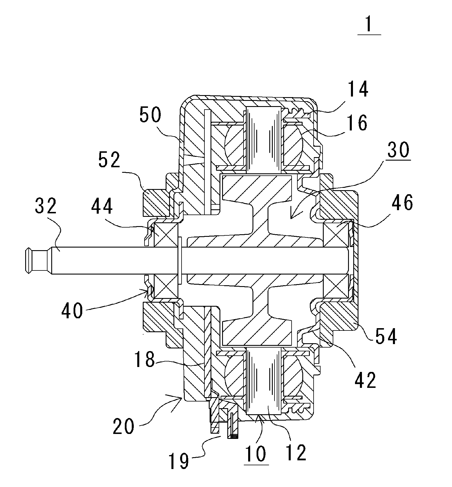
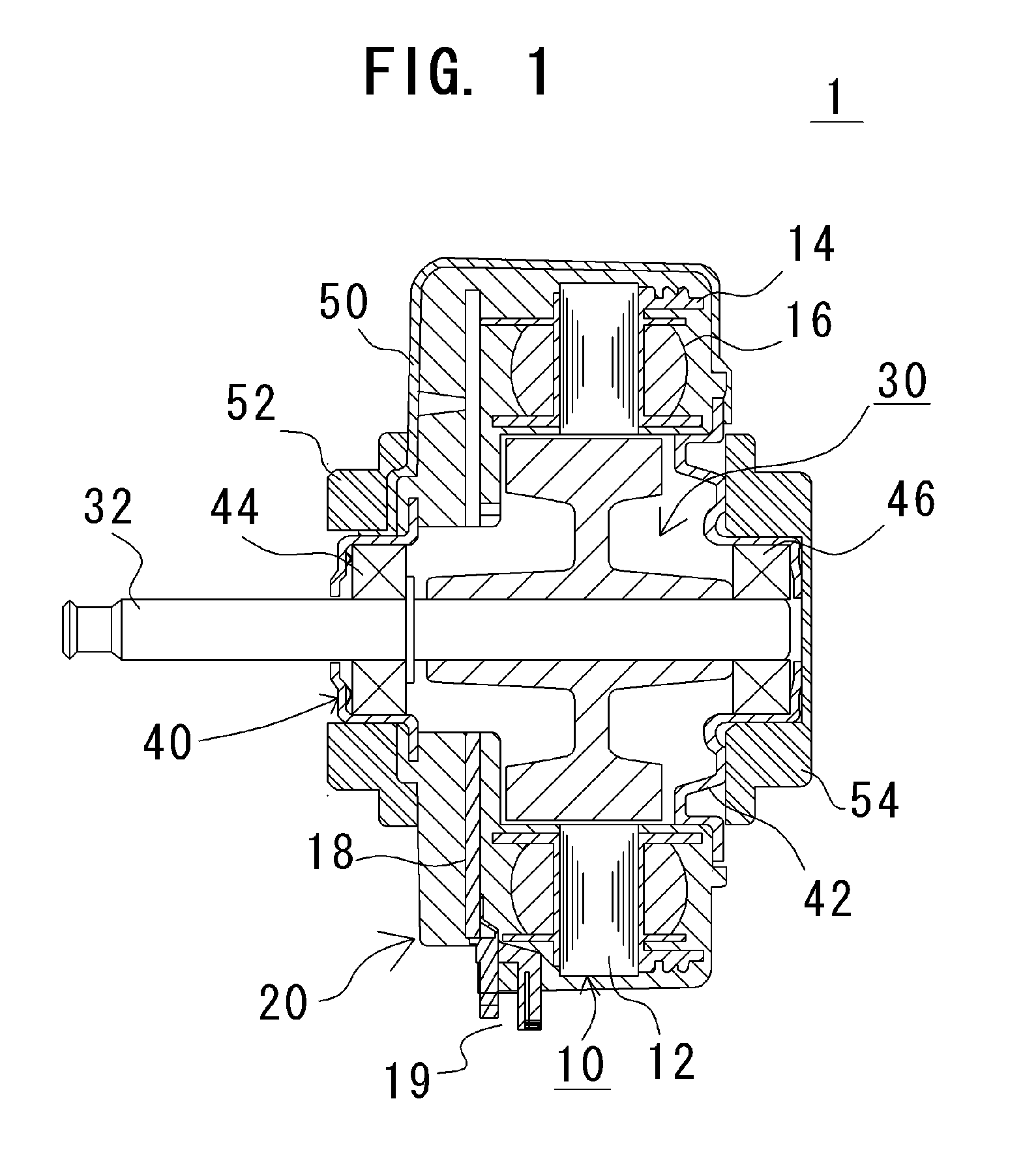
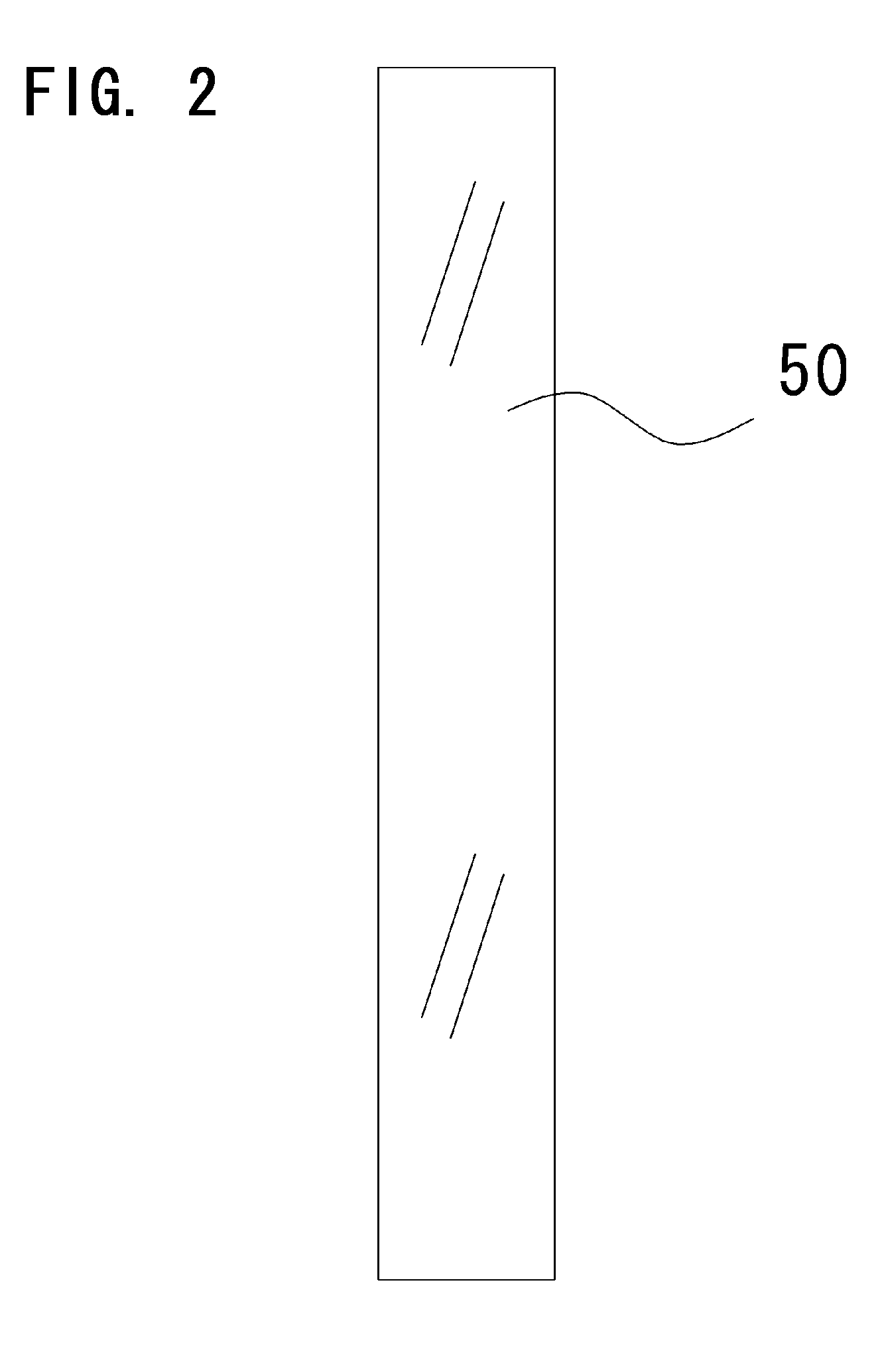
[0016]Referring to FIGS. 1 and 2, preferred embodiments of the present invention will be described in detail. It should be noted that in the explanation of the present invention, when positional relationships among and orientations of the different components are described as being up / down or left / right, ultimately positional relationships and orientations that are in the drawings are indicated; positional relationships among and orientations of the components once having been assembled into an actual device are not indicated. Meanwhile, in the following description, an axial direction indicates a direction parallel to a center axis of a motor, and a radial direction indicates a direction perpendicular to the rotation axis.

[0017]A molded motor according to a preferred embodiment of the present invention is now described referring to FIGS. 1 and 2.

[0018]In this preferred embodiment, the molded motor 1 preferably is a brushless DC motor. The molded motor 1 includes a motor frame 20 wi...


PUM


Abstract

An inner rotor type molded motor controlled by pulse width modulation using an inverter circuit includes a pair of electrically conductive brackets attached to a load-side portion and an anti-load-side portion of a motor frame. An electrically conductive tape is attached on the outside of the motor frame to extend between the brackets, thereby short-circuiting the brackets to each other. In this manner, electrical erosion in the molded motor can be prevented.

Description

BACKGROUND OF THE INVENTION[0001]1. Field of the Invention[0002]The present invention relates to an inner rotor type molded motor.[0003]2. Description of the Related Art[0004]A known molded motor has a motor frame made of insulating molding resin covering a stator, and a rotor is disposed on a center-axis side of the stator in a rotatable manner. The stator includes a stator core and a coil formed around a portion of the stator core which serves as a main magnetic path. The rotor includes a shaft centered on the center axis of the molded motor. The shaft is supported by ball bearings disposed at or near axial ends of the stator. Since the resin molding the stator forms the motor frame, the molded motors do not require a component that functions or defines an outer casing of the motor. Thus, the number of the components of the molded motor and the manufacturing cost thereof can be reduced.[0005]Typical molded motors use brushless DC motors. The brushless DC motors are usually control...

Claims


Application Information

Patent Timeline
IPC IPC(8): H02K5/02H02K1/04H02K11/00
CPCH02K5/08H02K11/0089H02K11/0005H02K11/40H02K11/0141
Inventor OKADA, TAKESHI
Owner NIDEC SHIBAURA CORP
Learn More