System and method for selectively extracting individual vials from an array of vials within a rack
What is Al technical title?
Al technical title is built by PatSnap Al team. It summarizes the technical point description of the patent document.
a rack and vial technology, applied in the field of biological or chemical sample storage systems, can solve the problems of substantially slow sample retrieval speed, and achieve the effect of minimizing temperature changes and minimizing gaps
Active Publication Date: 2008-02-21
NEXUS BIOSYSTEMS INC
View PDF56 Cites 14 Cited by
Summary
Abstract
Description
Claims
Application Information
AI Technical Summary
This helps you quickly interpret patents by identifying the three key elements:
Problems solved by technology
Method used
Benefits of technology
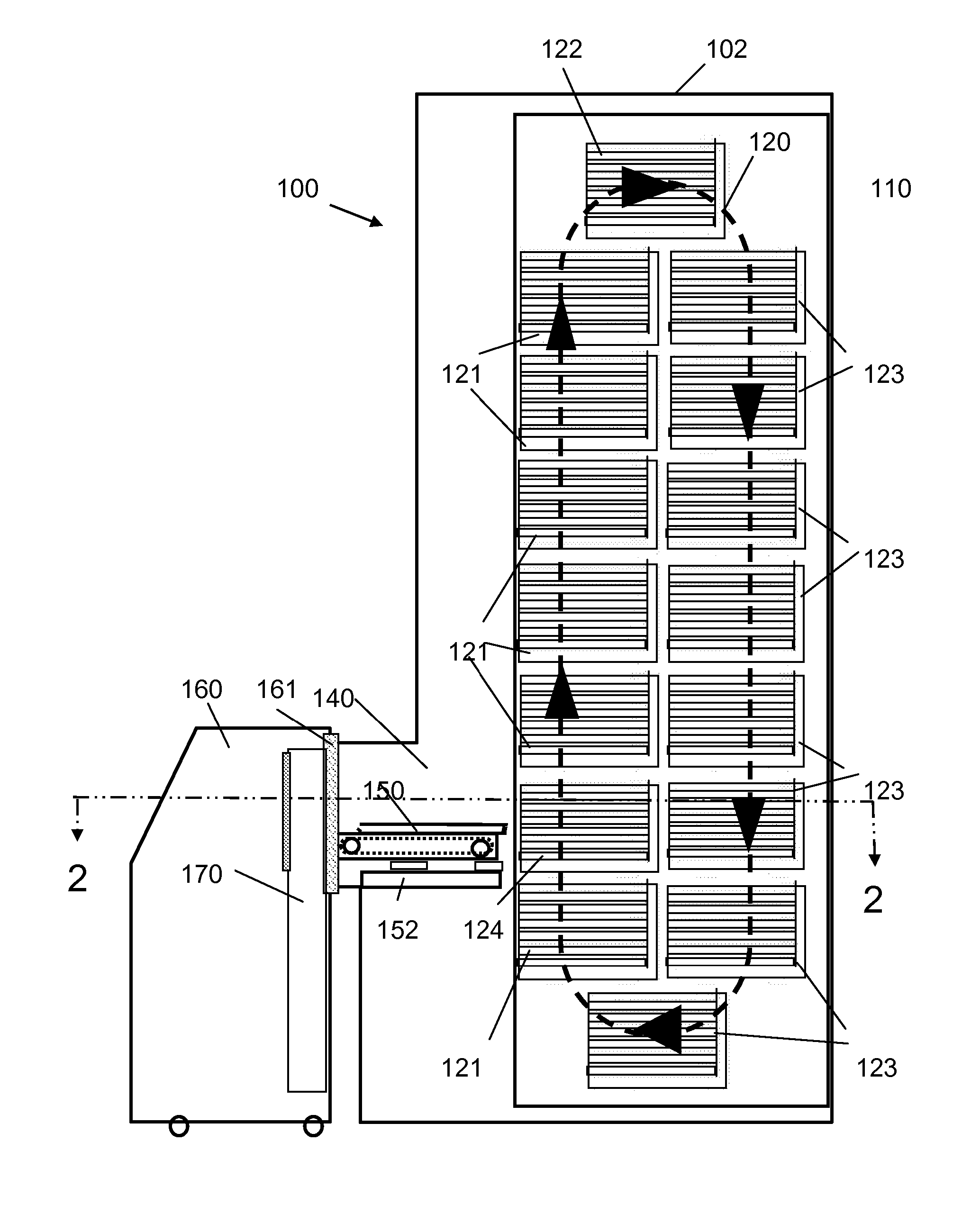
[0012] In a first exemplary embodiment, the automated sample storage and management system of the present invention employs a vertical storage carousel for the refrigerated storage compartment. Trays containing one or more arrays of individual, removable sample containers fit into a plurality of slots located in carriers that rotate around the carousel. The slots are configured to permit sufficient clearance between vertically adjacent trays to accept a variety of different size sample containers or well plates. The vertical carousel reduces the footprint of the system and greatly improves reliability since the carousel operation requires only a single motor that provides forward or reverse rotation to position the desired tray, or tray slot, in alignment with a horizontal tray loader / unloader mechanism, or “shuttle.
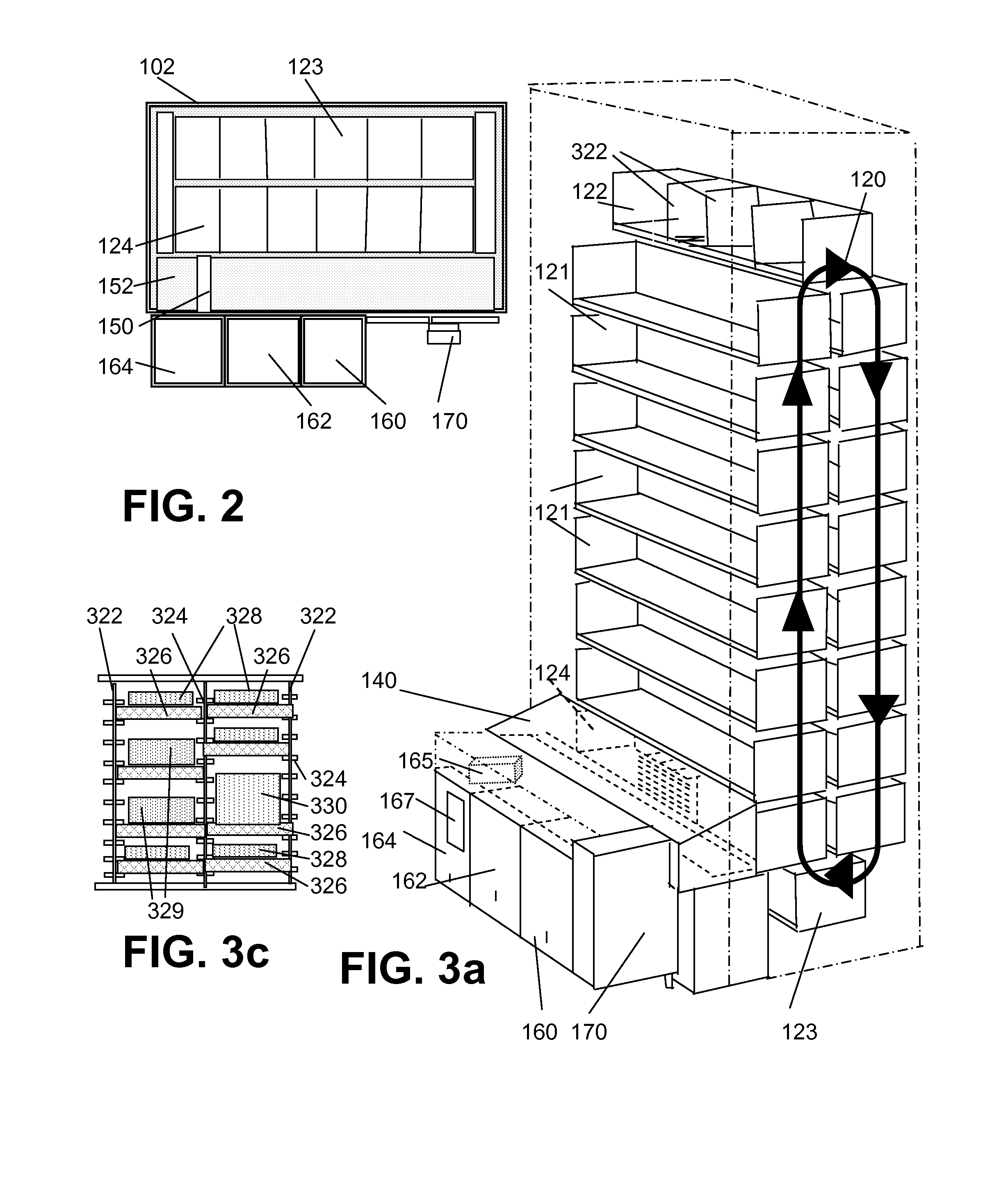
[0023] In an alternate embodiment of the storage compartment that is particularly suitable for ultra cold storage, the vertical carousel is replaced by stationary racks and a gantry-type tray shuttle, capable of vertical and horizontal movement, which is housed within a warmer (˜−20° C.) compartment. The storage compartment is separated from the tray shuttle / gantry compartment by stacks of foam bricks that are arranged to create a robotically friendly insulating wall in front of the storage trays. The blocks are arranged in stacks and held in place by gravity. Guide rails on either side of the stacks constrain the blocks against lateral movement while allowing them to slide up and down freely. To access a particular tray, the robotic loader / unloader moves to a block in front of the desired tray, extends a pin or plate into a corresponding recess in the block, then lifts all of the blocks above that point. The tray of interest is extracted and the blocks are lowered to the original position. The blocks can be of any size but it is preferable to keep them relatively small to minimize size of the gap needed to access the desired tray position and, thus, minimize any temperature change that might occur when the gap is temporarily opened in the wall. The inventive approach allows the opening to be immediately closed after the tray is extracted, without the delays experienced with prior art systems that require a substitute tray to be retrieved to plug the hole left by the extracted tray.
Problems solved by technology
They can retrieve trays quickly when the requested samples are located near each other, but become substantially slower when retrieving samples stored at the most distant locations of the storage area.
Method used
Image
Click on the blue label to locate the original text in one second.
Reading with bidirectional positioning of images and text.
Examples
Embodiment Construction
[0041] For purposes of the detailed description of the preferred embodiments, the following definitions are used:
[0042] A “sample” is used to describe a material (compound, biological specimen, or other substance) that is or can be stored in a storage system, as well as a tube, vial and similar container which is the lowest unit of storage for retaining the stored material.
[0043] An “array” includes plates and racks that organize samples in a fixed arrangements. Racks hold removable sample containers while plates have non-removable wells. Such racks are generally configured as an array of vertical, open ended sleeves or slots, permitting access to the removable containers retained within the slots.
[0044] A “tray” is a flat frame or container the holds multiple arrays. Generally, all trays within the storage system will be of the same length and width, and the arrays within a given tray will all have the same size sample. Exemplary trays have footprints to receive up to six standa...
PUM
Abstract
An automated storage system for storing large quantities of samples in trays includes a storage compartment, a tray shuttle compartment abutting the storage compartment on one side and a plurality of independent modules on the other side. The modules perform processing of samples that are retrieved from the storage compartment by a tray shuttle, including extraction of selected samples from retrieved source trays and transfer of the selected samples into a separate, destination tray that can be further processed or removed from the system for use. The independent operation of the modules permits handling and processing to be performed simultaneously by different modules while the tray shuttle accesses additional samples within the storage compartment. In one embodiment, a vertical carousel is used to vertically align a desired tray with the tray shuttle, while the tray shuttle operates within a horizontal plane.
Description
RELATED APPLICATIONS [0001] This application claims the benefit of the priority of U.S. Provisional Applications No. 60 / 761,736, filed Jan. 23, 2006, No. 60 / 799,706, filed May 11, 2006, No. 60 / 808,470, filed May 24, 2006, and No. 60 / 820,338, filed Jul. 25, 2006, each of which is incorporated herein by reference in its entirety.FIELD OF THE INVENTION [0002] The present invention relates for systems for handling and storing biological or chemical samples, and more specifically to an automated system for storage, retrieval and management of large numbers of samples retained in sealed arrays of storage containers. BACKGROUND OF THE INVENTION[0003] Many scientific and medical organizations, including industrial concerns, regulatory agencies, research laboratories, and academic institutions, have the need for secure storage of very large numbers, e.g., a few thousand up to multiple millions, of samples and specimens. Such fields include pharmaceutical, biotechnology, laboratory diagnostic...
Claims
Application Information
Patent Timeline
Application Date:The date an application was filed.
Publication Date:The date a patent or application was officially published.
First Publication Date:The earliest publication date of a patent with the same application number.
Issue Date:Publication date of the patent grant document.
PCT Entry Date:The Entry date of PCT National Phase.
Estimated Expiry Date:The statutory expiry date of a patent right according to the Patent Law, and it is the longest term of protection that the patent right can achieve without the termination of the patent right due to other reasons(Term extension factor has been taken into account ).
Invalid Date:Actual expiry date is based on effective date or publication date of legal transaction data of invalid patent.
Patent Type & Authority Applications(United States)