Power transmission device

a transmission device and power technology, applied in the direction of gear lubrication/cooling, belt/chain/gearing, gear lubrication, etc., can solve the problems of reducing oil level and unable to obtain sufficient oil bath lubrication at low rotational speed, so as to achieve good mechanical efficiency, low rotational speed, and good lubrication efficiency

Inactive Publication Date: 2008-02-21
NISSAN MOTOR CO LTD
View PDF2 Cites 32 Cited by
  • Summary
  • Abstract
  • Description
  • Claims
  • Application Information

AI Technical Summary

Benefits of technology

[0009]If the rate at which the oil level decreases is set to be low so that sufficient lubrication can be obtained by oil bath lubrication when the rotational speed of the gear mechanism (such as when the vehicle is starting into motion), then the oil level will still be somewhat high and oil bath lubrication will continue even when the rotational speed of the gear mechanism becomes comparatively high. The oil bath lubrication is not necessary because the higher rotational speed allows sufficient lubrication to occur by means of forced lubrication from the oil pump, and there is the possibility that the gradual linear decrease of the oil level will prevent the agitation resistance from being decreased efficiently.
[0011]One object of the present invention is to provide a power transmission device having good lubrication efficiency at comparatively low rotational speeds that require oil bath lubrication and good mechanical efficiency at comparatively high rotational speeds that enable forced lubrication. Thereby achieving a good balance between lubrication efficiency and mechanical efficiency as the rotational speed of the oil pump increases.

Problems solved by technology

Conversely, if the rate at which the oil level decreases is set to be high such that the agitation resistance can be prevented from increasing as the rotational speed increases, the oil level will decrease early and there is the possibility that sufficient oil bath lubrication will not be obtained at low rotational speeds.

Method used


Image

  • Power transmission device
  • Power transmission device
  • Power transmission device

Examples


second embodiment

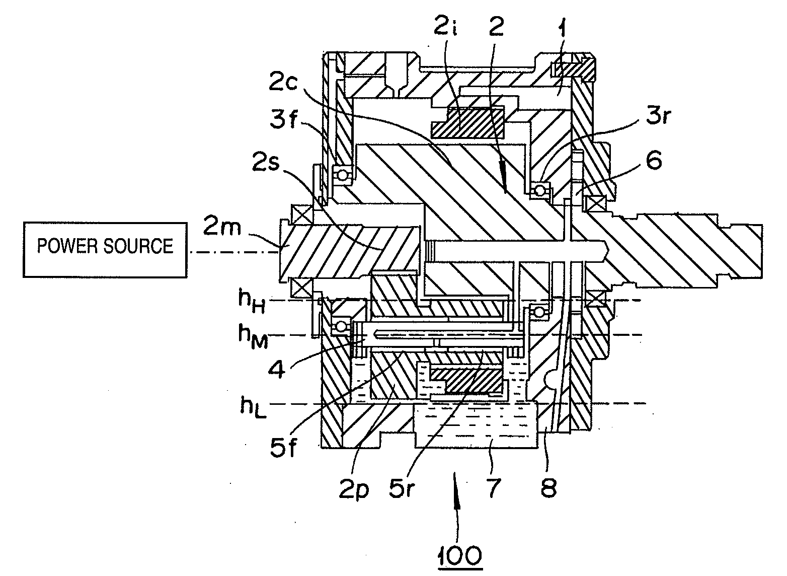
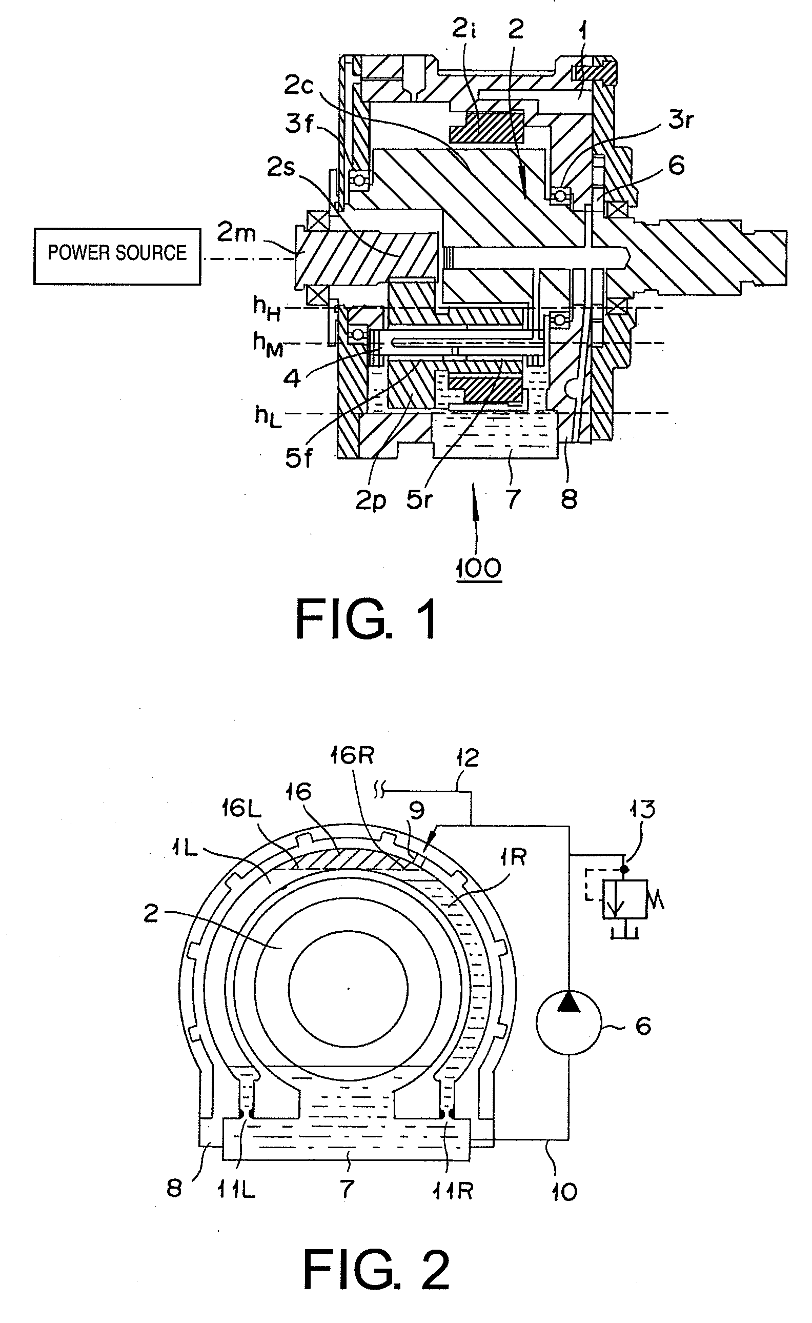
[0063]Referring now to FIGS. 6 and 7, a second embodiment of the present invention will now be explained. In view of the similarity between the first and second embodiments, the parts of the second embodiment that are identical or substantially identical to the parts of the first embodiment will be given the same reference numerals as the parts of the first embodiment. Unless otherwise stated, the parts of first and second embodiments are identical. Moreover, the descriptions of the parts of the second embodiment that are identical or substantially identical to the parts of the first embodiment may be omitted for the sake of brevity. Thus, the explanation will focus on the differences with respect to the first embodiment.

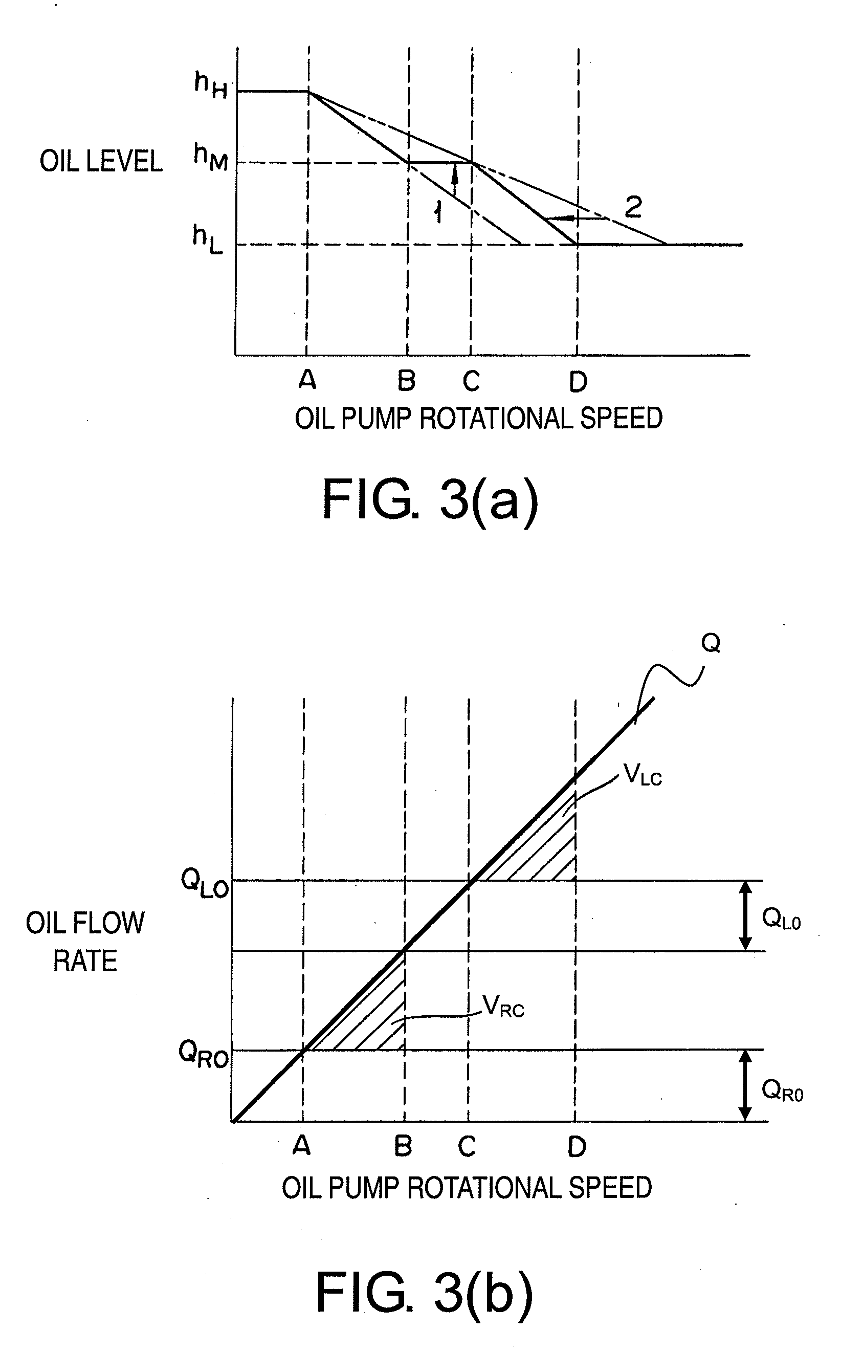
[0064]FIG. 6 is a transverse cross sectional view of a lubrication structure in accordance with the second embodiment of the present invention, the cross section lying in a plane perpendicular the center axis of the power transmission device. FIG. 7 is a graph showi...

third embodiment

[0077]Referring now to FIG. 10, a third embodiment of the present invention will now be explained. In view of the similarity between the third embodiment and the prior embodiments, the parts of the third embodiment that are identical or substantially identical to the parts of the first embodiment will be given the same reference numerals as the parts of the first embodiment. Unless otherwise stated, the parts of first and third embodiments are identical. Moreover, the descriptions of the parts of the third embodiment that are identical or substantially identical to the parts of the first embodiment may be omitted for the sake of brevity. Thus, the explanation will focus on the differences with respect to the first embodiment.

[0078]FIG. 10 is a transverse cross sectional view of a power transmission device in accordance with the third embodiment. The cross section lies in a plane perpendicular to the center axis of the power transmission device. The lubrication structure and lubricat...


PUM


Abstract

A power transmission device is provided with a gear mechanism, a case, an oil pump and an oil tank. The gear mechanism is arranged to operate in coordination with a drive source. The case houses the gear mechanism and stores oil for lubricating the gear mechanism. The oil pump is arranged to operate in coordination with the drive source so as to pump the oil stored in the case to lubricate the gear mechanism. The oil tank is arranged to collect a portion of the oil pumped from the oil pump. The oil tank includes a first discharge outlet arranged to discharge the oil collected in the oil tank to the case and a second discharge outlet arranged to discharge collected oil to the case when an amount of the oil collected in the oil tank is equal to or larger than a prescribed amount.

Description

CROSS-REFERENCE TO RELATED APPLICATIONS[0001]This application claims priority to Japanese Patent Application No. 2006-221661, filed on Aug. 15, 2006 and Japanese Patent Application No. 2007-147234, filed on Jun. 1, 2007. The entire disclosures of Japanese Patent Application No. 2006-221661 and Japanese Patent Application No. 2007-147234 are hereby incorporated herein by reference.BACKGROUND OF THE INVENTION[0002]1. Field of the Invention[0003]The present invention generally relates to a power transmission device. More specifically, the present invention relates to a power transmission device provided with a lubricating arrangement for lubricating a gear mechanism contained in a case of the power transmission device.[0004]2. Background Information[0005]A power transmission device used in a vehicle typically has a gear mechanism that is operated in coordination with a drive source (e.g., a motor) serving to drive the vehicle. The power transmission device has a case that houses the ge...

Claims


Application Information

Patent Timeline
Patent Type & Authority Applications(United States)
IPC IPC(8): F16H57/04F16H57/02
CPCF16H57/0436F16H57/0447F16H57/0486F16H57/0457F16H57/045
Inventor NISHIHARA, RYUUTA
Owner NISSAN MOTOR CO LTD
Why Eureka
Try Eureka