
Locking device for firearm

Inactive Publication Date: 2008-02-28
BARREL GUNLOCK
View PDF24 Cites 8 Cited by
  • Summary
  • Abstract
  • Description
  • Claims
  • Application Information

AI Technical Summary

Benefits of technology

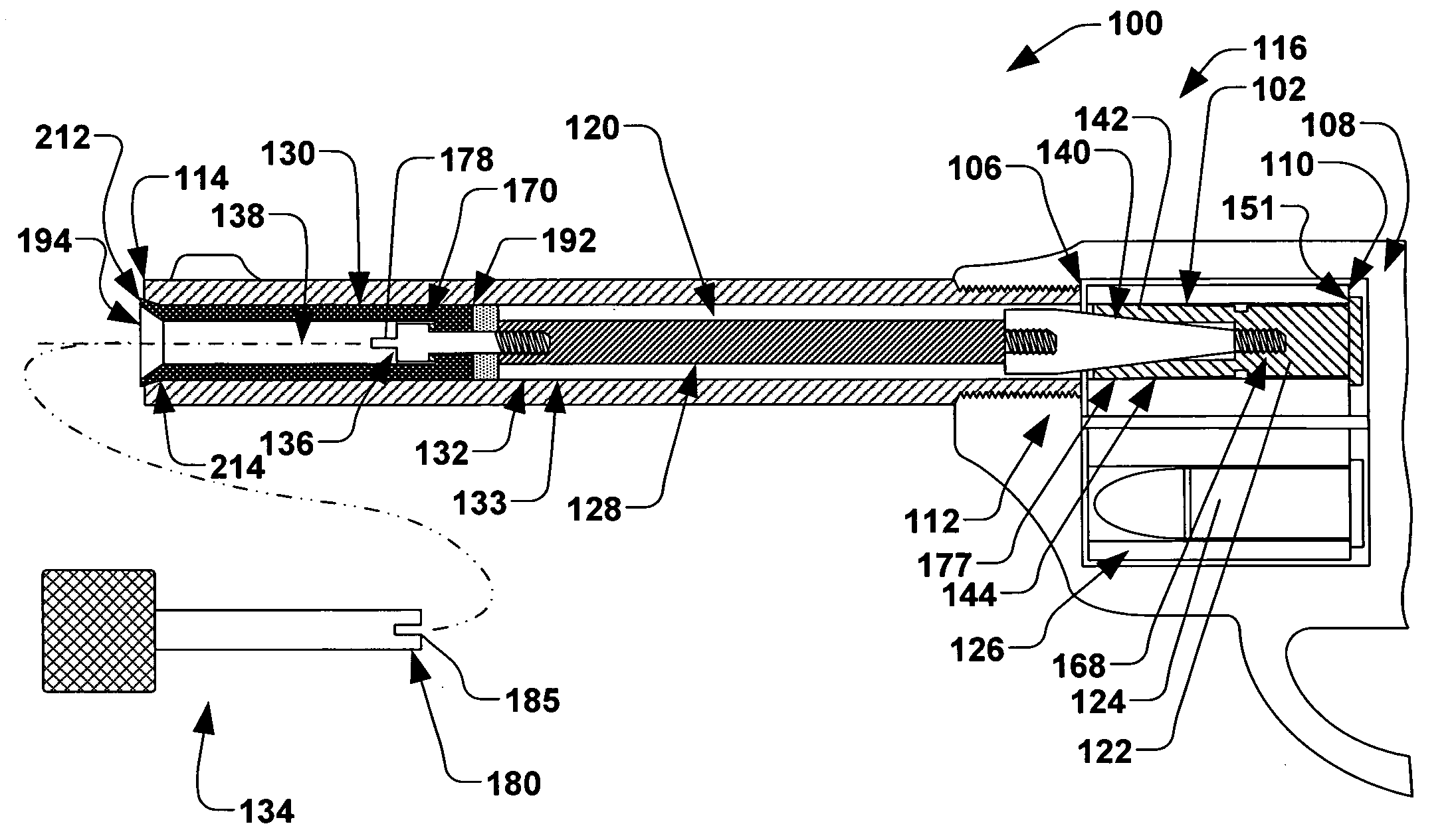
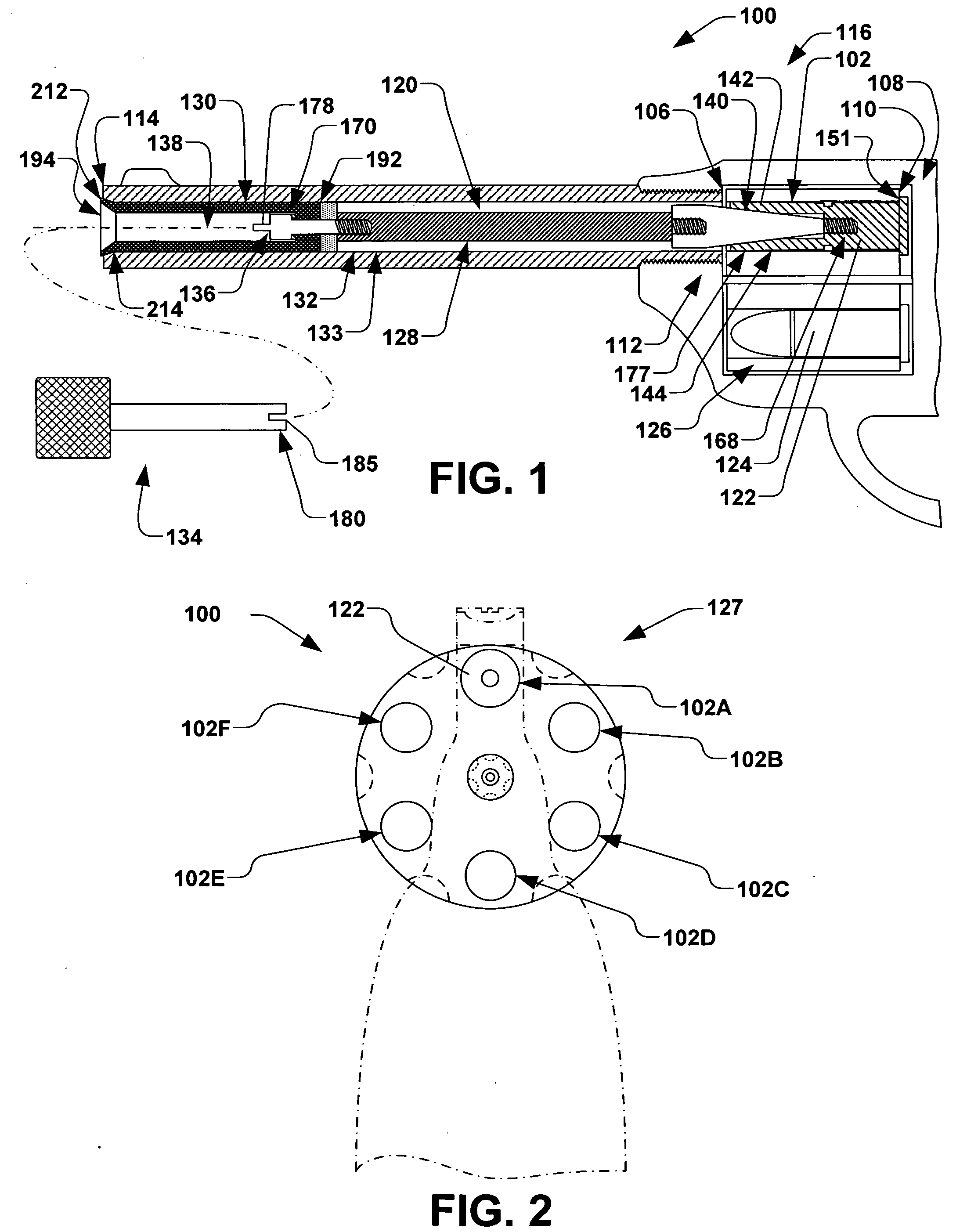
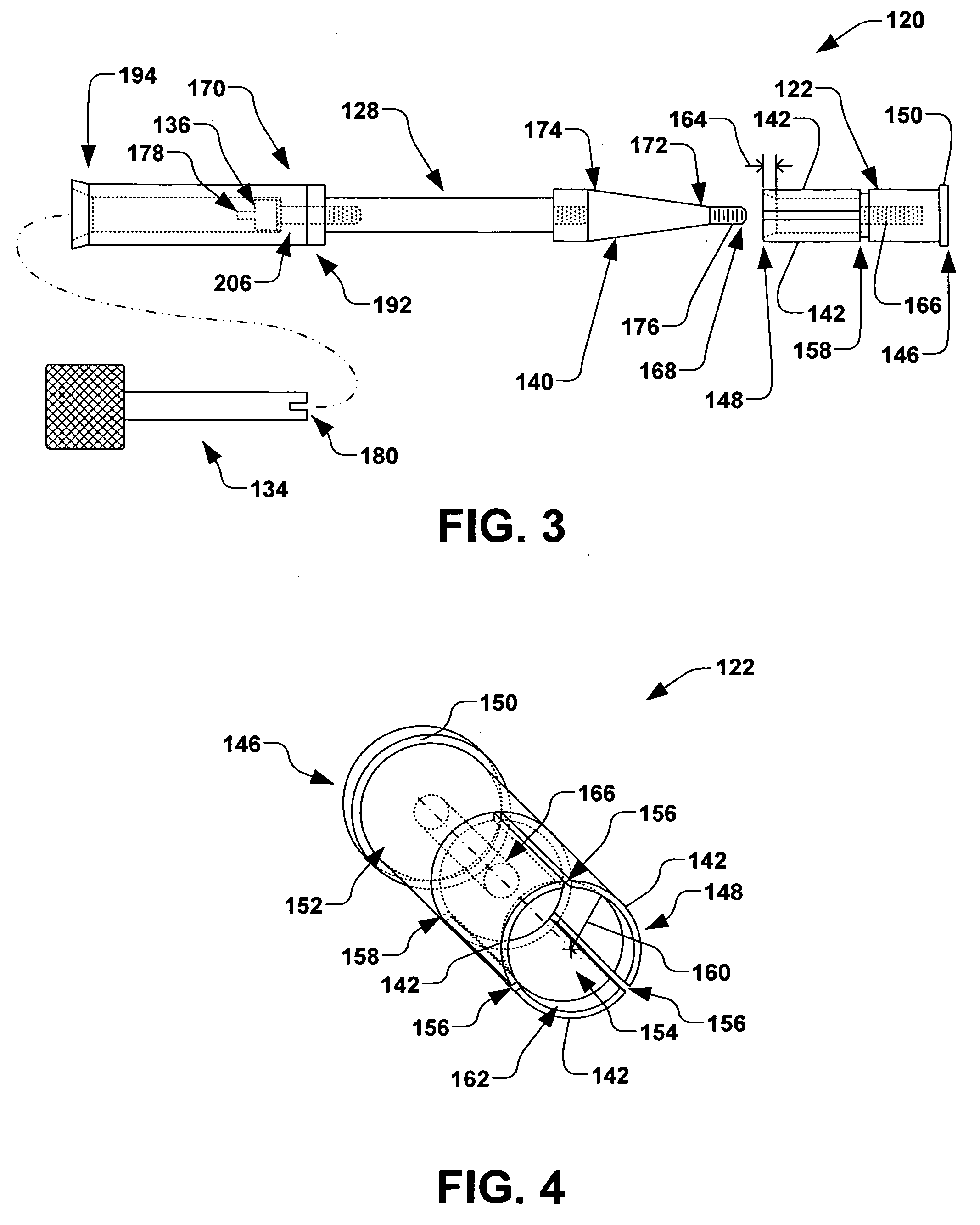
[0010]A removable tool comprising a shaft having first end and a second end is further provided, wherein the first end of the shaft comprises a second engagement member operable to be inserted into the protective cylinder and is configured to selectively mate with the first engagement member. An axial rotation of the tool is further operable rotate and linearly translate the cam based on the engagement between the internal thread and external thread, therein increasing an amount of friction in the first, second, and third friction regions. The increased friction thus locks the locking device with respect to the firearm, thus generally preventing a firing of the firearm, while providing an appearance of an unlocked firearm to the casual observer.

Problems solved by technology

When stored unlocked, or in the possession of a unauthorized, unintended, or careless person, however, the firearm can pose a significant threat to the safety of the public, and even to the person, themselves.
For example, a loaded firearm that has been carelessly left unlocked in a location such that a child could reach and handle the firearm can have catastrophic consequences.
Such locking devices, however, are not well suited for displayed collections of firearms, where the viewer of the collection may wish to admire the firearms as they would appear in his or her hand and about to fire, and without an obstructive locking device extending from the barrel.

Method used


Image

  • Locking device for firearm
  • Locking device for firearm
  • Locking device for firearm

Examples


Embodiment Construction

[0019]The present invention is directed generally toward a locking device for a firearm. Accordingly, the present invention will now be described with reference to the drawings, wherein like reference numerals may be used to refer to like elements throughout. It should be understood that the description of these aspects are merely illustrative and that they should not be interpreted in a limiting sense. In the following description, for purposes of explanation, numerous specific details are set forth in order to provide a thorough understanding of the present invention. It will be evident to one skilled in the art, however, that the present invention may be practiced without these specific details.

[0020]Referring now to the figures, FIG. 1 illustrates a partial view of an exemplary firearm 100, wherein several aspects of the present invention will now be discussed. The firearm 100 of the present example comprises a firing chamber 102 and an elongate barrel 104, wherein the firing ch...


PUM


Abstract

A device and method for locking a firearm are provided, the device having a locking round, elongate locking rod, protective cylinder, and locking tool. The locking round has a radial flange, an internal thread, and a plurality of prongs associated therewith, wherein the prongs are disposed about a circumference of the locking round. The locking rod has a conical cam, an external thread, and a first engagement member, wherein the cam is operable to radially expand the prongs through engagement between the internal and external threads. A removable tool having a second engagement member is operable to be inserted into the protective cylinder that is rotatably coupled to the locking rod, wherein a rotation of the tool is operable to operable to engage the shoulder, prongs, and protective cylinder with the firearm, thus providing first, second, and third friction regions for locking the locking device in the firearm.

Description

FIELD OF THE INVENTION[0001]The present invention relates generally to a safety lock for a firearm and a method for locking a firearm to selectively prevent firing thereof.BACKGROUND OF THE INVENTION[0002]In today's society, ownership of firearms quite common. When in the immediate possession of a responsible and qualified owner, a firearm can be used safely and properly for a multitude of purposes, such as for security or protection, hunting, sports such as skeet, trap, and target shooting, and even for collection or display. When stored unlocked, or in the possession of a unauthorized, unintended, or careless person, however, the firearm can pose a significant threat to the safety of the public, and even to the person, themselves. For example, a loaded firearm that has been carelessly left unlocked in a location such that a child could reach and handle the firearm can have catastrophic consequences. Accordingly, a variety of firearm locks have been introduced in an attempt to limi...

Claims


Application Information

Patent Timeline
IPC IPC(8): F41A17/00
CPCF41A17/44
Inventor RAMSEY, DONALD BRUCE
Owner BARREL GUNLOCK
Learn More