Steering apparatus

a technology of steering apparatus and backlash, which is applied in the direction of belt/chain/gearing, vehicle components, belt/chain/gearing, etc., can solve the problems of increasing the backlash between the two according to the degree of wear, and achieve the effect of facilitating the adjustment of the backlash, reducing the manufacturing cost and enhancing the rigidity of the feed screw mechanism

Inactive Publication Date: 2008-02-28
NSK LTD
View PDF10 Cites 24 Cited by
  • Summary
  • Abstract
  • Description
  • Claims
  • Application Information

AI Technical Summary

Benefits of technology

[0011]It is an object of the invention to provide a steering apparatus which can facilitate the adjustment of a backlash between a feed screw shaft and a feed nut and, even when the thread ridges of the feed screw shaft and feed nut provide

Problems solved by technology

Further, when the thread ridges of the feed screw shaft and feed nut are wore o

Method used


Image

  • Steering apparatus
  • Steering apparatus
  • Steering apparatus

Examples


embodiment 1

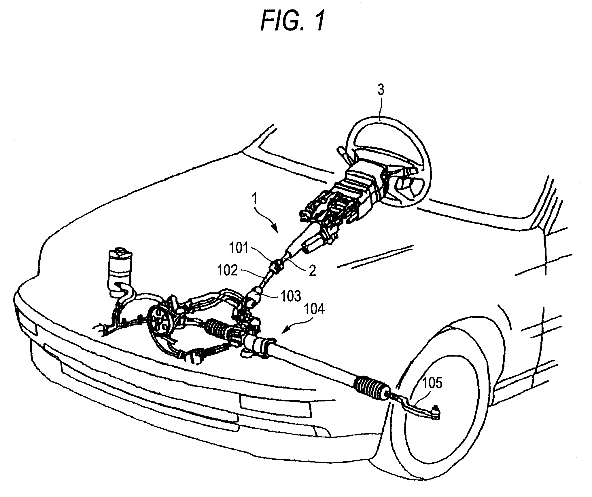
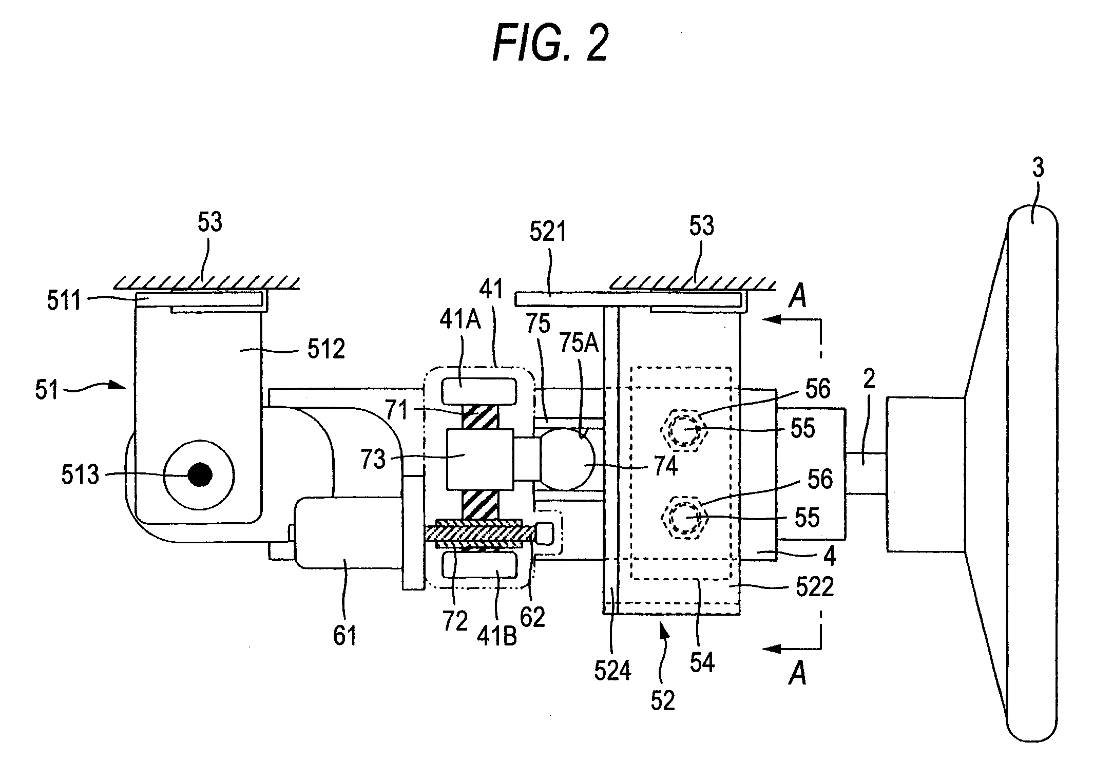
[0073]FIG. 1 is a general perspective view of a steering apparatus 1 according to the invention, showing a state in which it is mounted on a vehicle. As shown in FIG. 1, the steering apparatus 1 includes a steering shaft 2 which is rotatably supported. On the right end (on a rear side of a vehicle body) of the steering shaft 2, there is mounted a steering wheel 3 and to the left end (on the front side of a vehicle body) of the steering shaft 2, there is connected an intermediate shaft 102 through a universal joint 101.

[0074]To the left end of the intermediate shaft 102, there is connected a universal joint 103 and, to the universal joint 103, there is connected a steering gear 104 which is composed of a rack and pinion mechanism and the like.

[0075]When a driver rotationally operates the steering wheel 3, the rotation power of the steering wheel 3 is transmitted through the steering shaft 2, universal joint 101, intermediate shaft 102 and universal joint 103 to the steering gear 104,...

embodiment 2

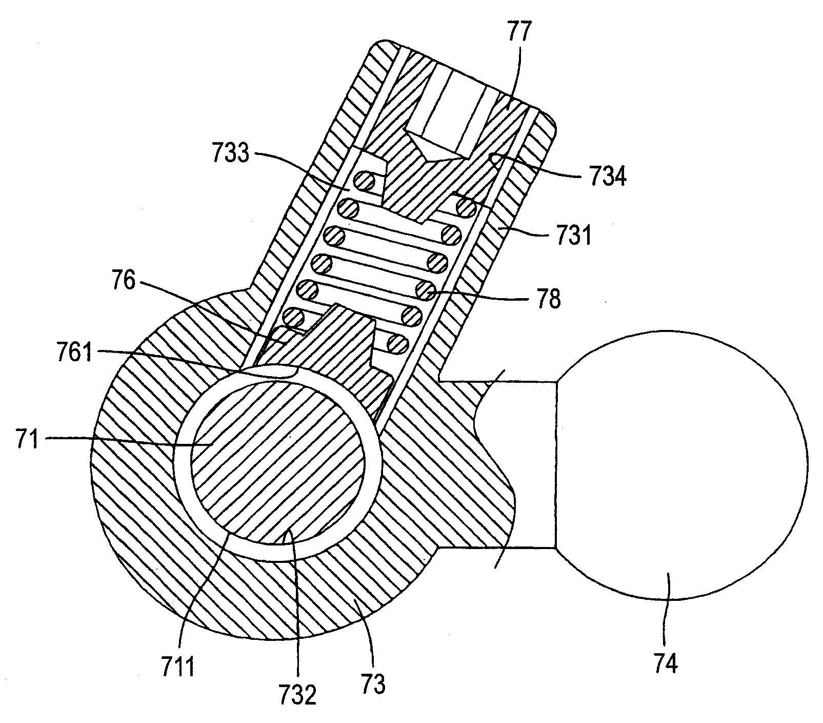
[0107]Next, description will be given below of another embodiment 2 according to the invention. FIG. 7 shows the main portions of a feed screw mechanism according to the embodiment 2 of the invention and corresponds to FIG. 8B. In the following description, only the portions of the embodiment 2, which are different from the above-mentioned embodiment 1, and the operations thereof will be described and the duplicate description of the same portions will be omitted.

[0108]The embodiment 2 shows a modification of the contact surface of the pressing member 76 with the outer diameter portion 711 of the feed screw shaft 71. In the embodiment 2, the contact surface of the pressing member 76 with the outer diameter portion 711 of the feed screw shaft 71 is formed as a V-shaped contact surface 762 which can be contacted with the outer diameter portion 711 of the feed screw shaft 71.

[0109]As shown by a circle designated by a one-dot chained line in FIG. 7, the contact surface 762 is contacted ...


PUM


Abstract

In the steering apparatus and feed screw mechanism, by properly adjusting the screw-in distance of a pressing force adjusting screw 77, the arc-shaped contact surface 761 of a pressing member 76 can be pressed against the outer diameter portion 711 of a feed screw shaft 71 with a required pressing force due to the biasing force of a compression coil spring 78. As a result of this, a backlash between a feed nut 73 and feed screw shaft 71 can be removed. Therefore, the telescopic position adjustment and tilt position adjustment of a steering wheel 3 can be carried out smoothly, thereby being able to enhance the rigidity of the steering wheel 3 after execution of the position adjustment thereof.

Description

[0001]The present invention claims foreign priority to Japanese patent application No. 2006-228473, filed on Aug. 24, 2006, the contents of which is incorporated herein by reference.BACKGROUND OF THE INVENTION[0002]1. Field of the Invention[0003]The present invention relates to a steering apparatus and, specifically, the invention relates to a steering apparatus which can adjust the tilt position or telescopic position of a steering wheel using the feed movement of a feed screw mechanism, and a feed mechanism used in the steering apparatus.[0004]2. Description of Related Art[0005]In a steering apparatus, it is necessary to adjust the tilt position or telescopic position of a steering wheel according to the build or driving attitude of a driver. There is known a steering apparatus including a feed screw mechanism which adjusts the tilt position or telescopic position by rotating a feed screw shaft through the rotation of an electric motor to thereby move linearly a feed nut threadedl...

Claims


Application Information

Patent Timeline
IPC IPC(8): F16H35/00B62D1/18
CPCF16H25/2009B62D1/181
Inventor TOMARU, MASAKIYONEZAWA, KOUHEIMURAMATSU, HIROYUKI
Owner NSK LTD
Why Eureka
Try Eureka