Peak voltage detector circuit and binarizing circuit including the same circuit

a detector circuit and circuit technology, applied in the direction of ac/pulse peak value measurement, measurement devices, instruments, etc., can solve the problem of not being able to detect the bottom voltage of the input voltage v/sub>in /sub>, and achieve the effect of accurate detection and accurate binarization

Inactive Publication Date: 2008-02-28
DENSO CORP
View PDF0 Cites 10 Cited by
  • Summary
  • Abstract
  • Description
  • Claims
  • Application Information

AI Technical Summary

Benefits of technology

The patent text describes a circuit that can accurately detect the peak voltage and binarize the input voltage. This means that the circuit can accurately measure the voltage and convert it into a digital format.

Problems solved by technology

The technical problem addressed in this patent is the accurate detection of peak voltage in a physical phenomenon using a sensor, even when the measured voltage has a rapidly varying part due to temperature variation.

Method used


Image

  • Peak voltage detector circuit and binarizing circuit including the same circuit
  • Peak voltage detector circuit and binarizing circuit including the same circuit
  • Peak voltage detector circuit and binarizing circuit including the same circuit

Examples


first embodiment

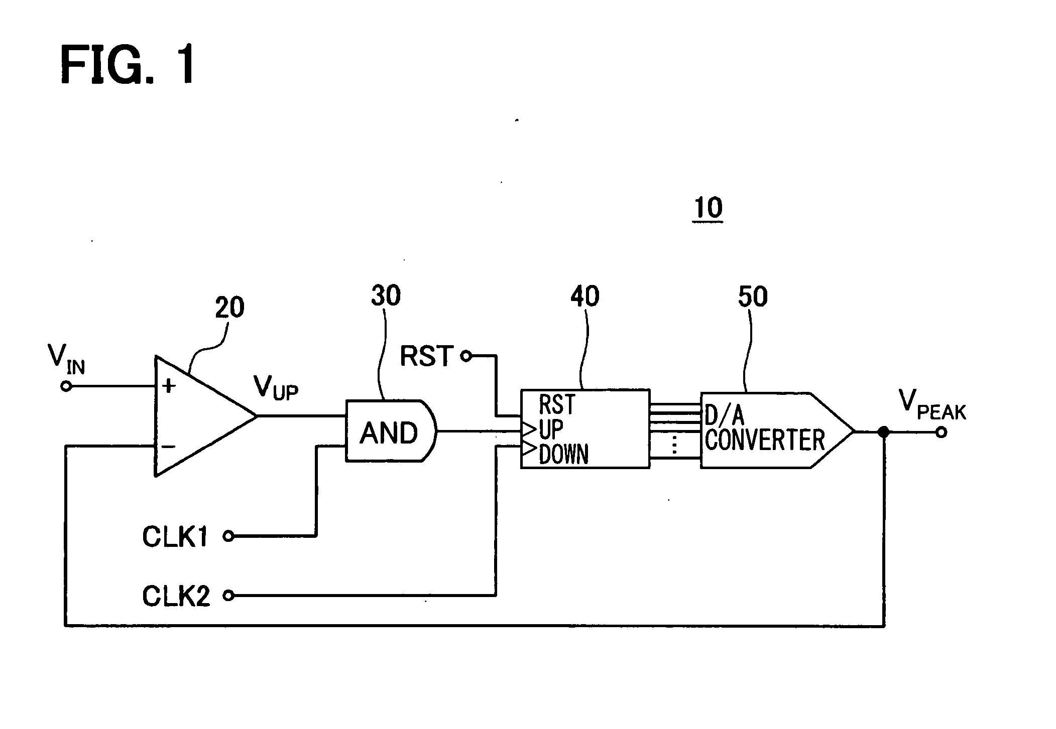
[0030] As shown in FIG. 1, a positive peak voltage detector circuit 10 for detecting a peak voltage, i.e., voltage convex upward, includes a comparator 20, an AND circuit 30, a counter circuit 40, a digital / analog (D / A) conversion circuit 50, a first clock signal generating circuit and a second clock signal generating circuit. The first clock signal generating circuit generates a first clock signal CLK1, and a wave period of the first clock signal CLK1 is shorter than that of a second clock signal CLK2 generated by the second clock signal generating circuit. Each frequency of the first clock signal CLK1 and the second clock signal CLK2 is set in accordance with a physical phenomenon of an object to be measured.

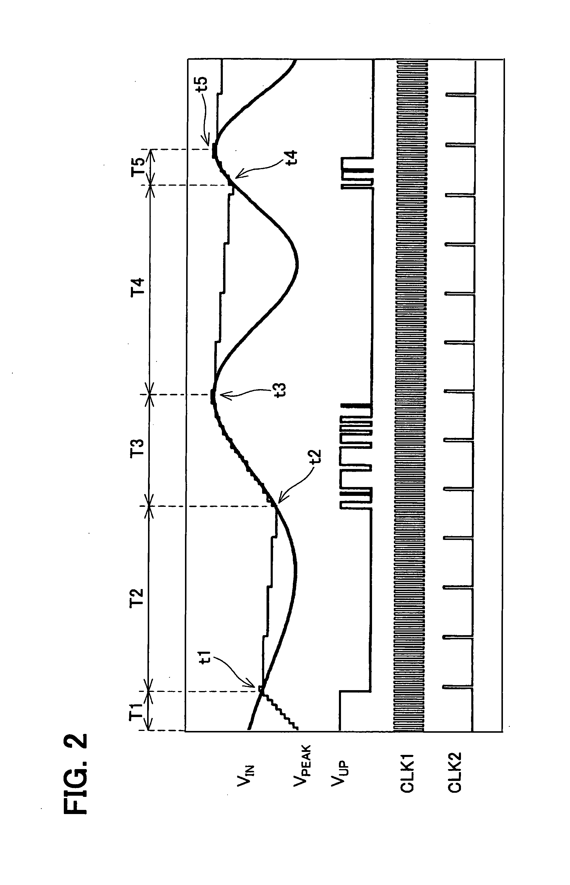
[0031] An input voltage VIN is input into a noninversion input terminal of the comparator 20, and an output voltage VPEAK output from the D / A conversion circuit 50 is input into an inversion input terminal of the comparator 20. The input voltage VIN has an alternating wavefor...

second embodiment

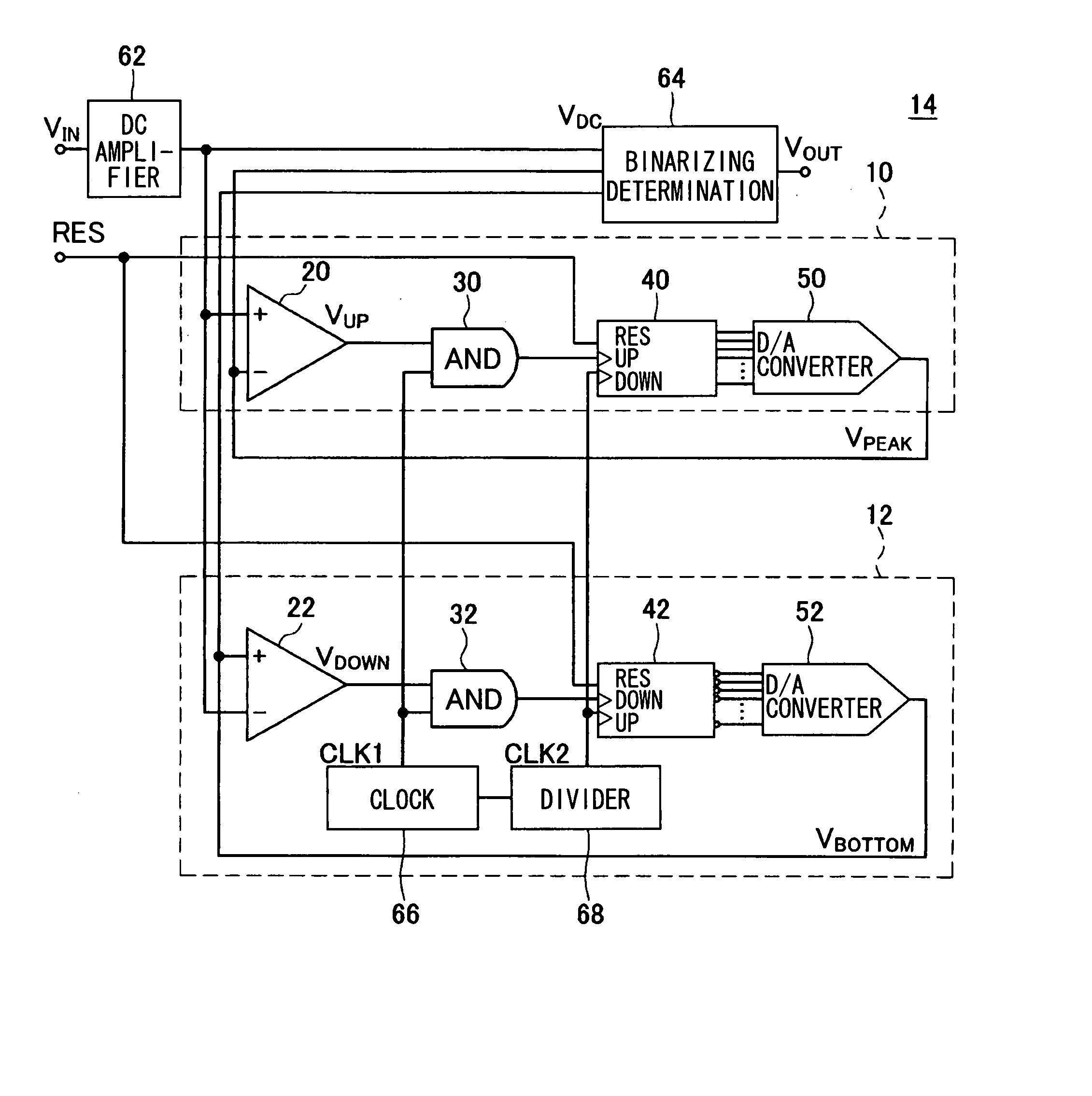
[0053]FIG. 7 shows a binarizing circuit 14. The binarizing circuit 14 includes the positive peak voltage detector circuit 10 shown in FIG. 1, the negative peak voltage detector circuit 12 shown in FIG. 5, a binarizing determination circuit 64 and a direct-current (DC) amplifier circuit 62. The binarizing circuit 14 further includes a clock circuit 66 and a frequency divider circuit 68. The clock circuit 66 generates a first clock signal CLK1. The frequency divider circuit 68 converts the first clock signal CLK1 having high-frequency into a second clock signal CLK2 having a low-frequency. The DC amplifier circuit 62 amplifies an input voltage VIN into an input voltage VDC.

[0054] The binarizing determination circuit 64 calculates an intermediate value as a threshold voltage by using the output voltage VPEAK detected by the positive peak voltage detector circuit 10 and the output voltage VBOTTOM detected by the negative peak voltage detector circuit 12. The binarizing determination ci...


PUM


Abstract

A peak voltage detector circuit detects a peak voltage of an input voltage. The input voltage is input into a first input terminal of a comparator. A counter circuit counts up a counter value in synchronization with a first clock signal, when a signal output from the comparator is in a first state. The counter circuit counts down the counter value in synchronization with a second clock signal. A digital-analog conversion circuit outputs an output voltage corresponding to the counter value, and the output voltage is input into a second input terminal of the comparator. The first clock signal has a wave period shorter than that of the second clock signal.

Description


Claims


Application Information

Patent Timeline
Owner DENSO CORP
Why Eureka
Try Eureka