CCFL Illuminated Device And Method Of Use

a fluorescent lamp and illuminated device technology, applied in the direction of light source combinations, instruments, roads, etc., can solve the problems of many limitations inherent in led performance, dimmed to very low light output, and limited led performance in illuminated signage and traffic signals

Inactive Publication Date: 2008-02-28
MARSH BRENT
View PDF54 Cites 62 Cited by
  • Summary
  • Abstract
  • Description
  • Claims
  • Application Information

AI Technical Summary

Benefits of technology

[0016] The present invention is a cold cathode fluorescent lamp (CCFL) illuminated sign, the sign operating off a main source of electrical power. The sign comprises a CCFL, the CCFL being elongated and having a predetermined length, the CCFL having a first end and a second, the CCFL having a fast electrode at the fast end and a second electrode at the second end. The sign also comprises an outer tubular housing, the housing essentially transparent, the housing having a first end and a second end, the tubular housing having a predetermined length essentially the same as that of the CCFL, the tubular housing having a central hollow opening, the CCFL disposed within the tubular housing. The sign also has two end fittings, the end fittings each having a small central opening axially the rethrough, the end fittings each comprising a lamp side and a contact side, the lamp side designed to receive a first end or a second end of the CCFL within the small central opening, the end fittings each having a radially spaced lip around the small central opening, the lip shaped to receive the first end or the second end of the outer tubular housing and hold the end radially spaced from the CCFL, the end fittings each having an attachment means for mounting the end fitting onto the CCFL and tubular housing. The sign also has CCFL mounting means, the CCFL mounting means comprising a pair of resilient prong members which grasp the end fittings securely and releasably. The sign also has a ballast means, the ballast means comprising an electrical circuit and associated electronics including control means, the ballast means having an input and an output, the input being connected to the main source of electrical power, the output connected to the CCFL electrodes, the ballast receiving a predetermined electrical input and producing an electrical output sufficient to stimulate the CCFL to produce illumination. The sign also has a housing, the housing comprising the following: a top portion; a base portion; a plurality of side members, the CCFL mounting means attached to either the top portion, the base portion or one of the plurality of side members; a plurality of viewing panels, the viewing panels bearing illuminated graphic indicia; and a housing mounting means, the housing mounting means providing a sturdy, convenient mounting for the illuminated sign.
[0022] The invention further includes a cold cathode fluorescent lamp (CCFL) illuminated A-lamp shaped light bulb, bulb utilizing a main power source, the bulb comprising a CCFL, the CCFL being elongated and having a predetermined length and geometric configuration, the CCFL having a fast end and having a second end, the CCFLs each having a first electrode at the fast end and a second electrode at the second end. There is an A-lamp shaped body portion, the A-lamp shaped body portion made of a suitable transparent material. There is a CCFL mounting means, the CCFL mounting means gasping the CCFL securely for mounting within the A-lamp shaped body portion. There is a ballast means, the ballast means comprising an electrical circuit and associated electronics including control means, the ballast means having an input and an output, the input being connected to the main source of electrical power, the output connected to the CCFL electrodes, the ballast receiving a predetermined electrical input and producing electrical outputs sufficient to stimulate the CCFL to produce illumination. There is a bulb mounting socket base portion, the socket base portion having a predetermined geometric configuration, the bulb mounting socket base portion further comprising a plurality of electrical contacts, the contacts connected to the input to the ballast, the contacts configured as in the contacts on the base of a conventional incandescent A-lamp light bulb. Numerous other advantages and features of the present invention will become readily apparent from the following detailed description of the invention and the embodiments thereof, from the claims and from the accompanying drawings in which the details of the invention are fully and completely disclosed as a part of this specification.

Problems solved by technology

Also, they may be dimmed to very low levels of light output.
However, there are many limitations to performance inherent with LEDs.
Performance of LEDs in illuminated signage and traffic signals is limited because LEDs emit light directionally and only in discrete colors, such as red, green and yellow.
Due to the directionality of the light output of LED and the color limitations, applications are restricted.
Due to the variable brightness, green and other colors are not readily adaptable in may applications.

Method used


Image

  • CCFL Illuminated Device And Method Of Use
  • CCFL Illuminated Device And Method Of Use
  • CCFL Illuminated Device And Method Of Use

Examples


Embodiment Construction

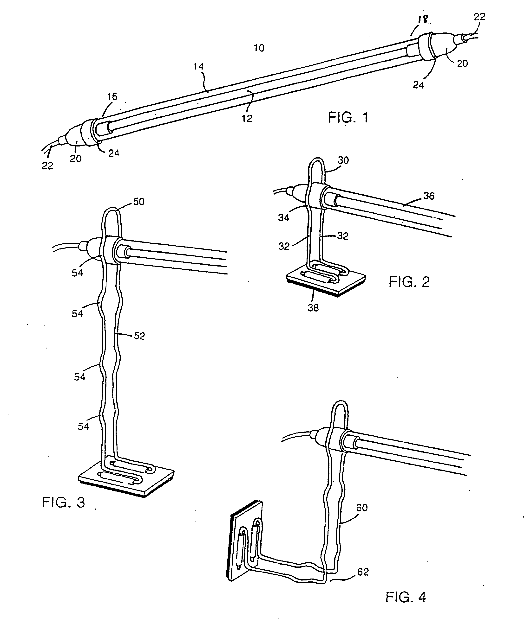
[0045]FIG. 1 is a perspective view of a preferred embodiment of the CCFL lamp assembly 10 of the present invention. The assembly consists of a CCFL lamp 12, held inside an outer tubular housing 14 at a first end 1615 and a second end 18. The CCFL lamp is supported and held in place inside the end fittings 20. These end fittings can be any type of fitting which will hold a lamp in place, preferably with some degree of support to protect against vibration, etc. In a preferred embodiment, they consist of small rubber or plastic grommets or bushings which fit inside either end of the outer tubular housing 14. The CCFL lamp 12 is supported inside the grommet and contact lead wires 22 can be installed in electrical contact with the electrodes of the lamp. An outer groove 24 on the outside of the grommet element is designed for use in lamp holders or other systems in which a thin wire or loop of other material might grip the lamp assembly at that point. The following table is a list of CCF...


PUM


Abstract

Cold cathode fluorescent lamps (CCFLs), associated devices and methods of use, and more specifically, exit signs, traffic signals, informational and other signage and lighting devices utilizing CCFL-type devices are provided with novel connectors, mounting brackets, housings, associated electronics and other accessories to provide new and unique lighting devices and methods of using them, all of which offer significant savings in cost, operating expense, power consumption and retrofit convenience.

Description

CROSS-REFERENCE TO RELATED APPLICATIONS [0001] This application is a continuation of U.S. patent application Ser. No. 10 / 944,818, filed Sep. 21, 2004, which is a continuation of U.S. patent application Ser. No. 10 / 414,714 filed Apr. 15, 2003, now U.S. Pat. No. 6,793,381, which is a continuation of U.S. patent application Ser. No. 09 / 598,009, filed Jun. 20, 2000, now U.S. Pat. No. 6,616,310, which is a continuation-in-part of U.S. patent application Ser. No. 08 / 630,361, filed Apr. 10, 1996, now U.S. Pat. No. 6,135,620.FIELD OF THE INVENTION [0002] This invention relates generally to miniature cold cathode fluorescent lamps (CCFLs) and other miniature fluorescent lamps, associated devices and methods of use, and more specifically, to exit signs, informational and other signage and lighting devices utilizing CCFL-type devices in conjunction with novel connectors, mounting brackets, housings and other accessories to provide new and unique lighting devices and methods of using them, all ...

Claims


Application Information

Patent Timeline
Patent Type & Authority Applications(United States)
IPC IPC(8): F21V15/00B01F7/00B01F7/08B01F13/00B01F13/10B01F15/00G09F13/00G09F13/04G09F13/18G09F13/26
CPCF21V19/008F21W2111/02F21Y2103/00G09F13/00G09F2013/0472G09F13/18G09F13/26G09F2013/0459G09F13/04F21V7/005F21V17/04F21Y2113/00G09F2013/05G09F13/0472
Inventor MARSH, BRENT
Owner MARSH BRENT
Why Eureka
Try Eureka