Gas generator for air bag and air bag device

a gas generator and air bag technology, applied in the direction of pedestrian/occupant safety arrangement, vehicular safety arrangment, vehicle components, etc., can solve the problems of unfailingly supporting and fixing the retainer, and the conventional gas generator is still susceptible to improvemen

Inactive Publication Date: 2003-07-17
DAICEL CHEM IND LTD
View PDF10 Cites 21 Cited by
  • Summary
  • Abstract
  • Description
  • Claims
  • Application Information

AI Technical Summary

Problems solved by technology

However, the conventional gas generator is still susceptible to improvement for enhancing the ignition performance of the gas generating agent.
In this case, the retainer receives pressure

Method used


Image

  • Gas generator for air bag and air bag device
  • Gas generator for air bag and air bag device
  • Gas generator for air bag and air bag device

Examples


Embodiment Construction

[0104] A gas generator for an air bag of the present invention will be explained based on the drawings showing preferred embodiments.

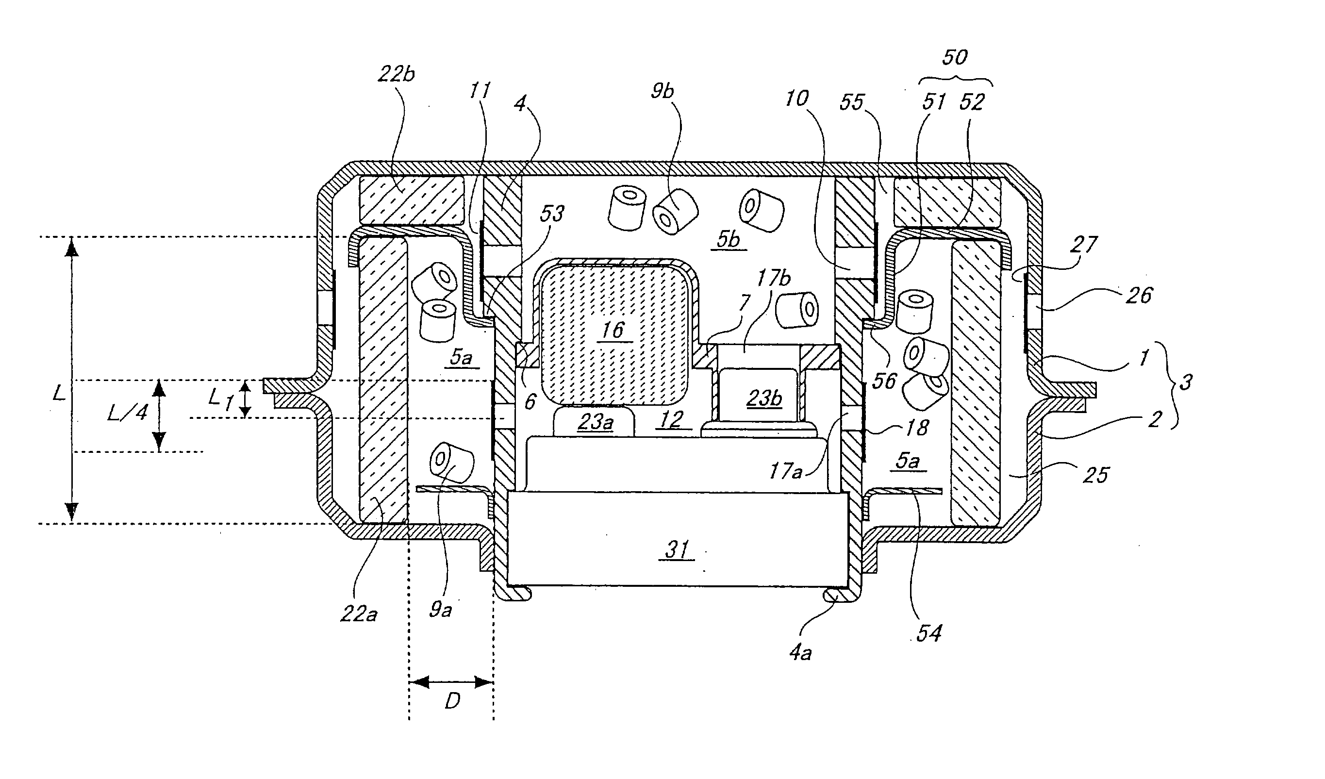
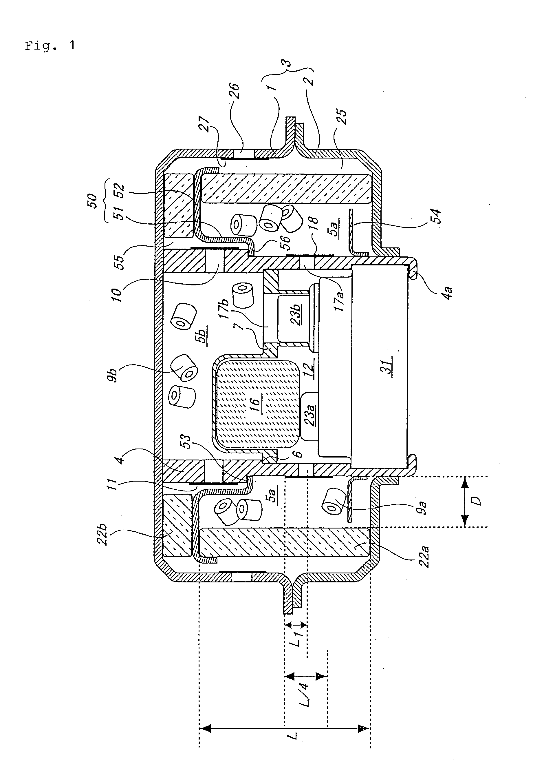
[0105] FIG. 1 is a vertical sectional view showing one embodiment of the gas generator for the air bag of the present invention.

[0106] The gas generator shown in this embodiment has two combustion chambers in a housing and two ignition means respectively corresponding to the combustion chambers. More specifically, in the housing 3 formed by joining a diffuser shell 1 having the gas discharging port 26 and a closure shell 2 forming an inner accommodating space together with the diffuser shell 1, an inner cylindrical member 4 in a substantially cylindrical shape is disposed and the outside thereof is a first combustion chamber 5a. An interior of the inner cylindrical member 4 is divided into two chambers by a partition wall 7, one chamber closer to the diffuser shell is a second combustion chamber 5b and the other chamber closer to the closure shell is a...


PUM


Abstract

The present invention provides a gas generator in which ignition and combustion performance of a gas generating agent and operation performance are enhanced. An inner cylindrical member 4 is disposed in a cylindrical housing 3, an annular first combustion chamber 5a is provided radially in the outside of the inner cylindrical member 4, and, in the combustion chamber 5a, a ratio (D/L) of its radial average distance (D) to its axial average length (L) is adjusted to be in the range of 0.2 to 2.0. The invention provides a gas generator for an air bag capable of reducing a size of the gas generator and easily and reliably adjusting a capacity of a combustion chamber which accommodates the gas generating agent, and also provides a retainer for such a gas generator. The invention provides a retainer which changes a flow of a gas ejected from a through-hole of an inner cylindrical member provided in the housing and has a cylindrical portion for collecting fluid and semifluid combustion products included in the gas, and provides a gas generator for an air bag using such a retainer. The invention provides a gas generator for an air bag comprising, in a housing having a gas discharging port, a inner cylindrical member having a cylindrical peripheral wall, and two combustion chambers defined by the inner cylindrical member, in which a gas generating agent to be ignited for generating a working gas is charged in the respective combustion chambers, and working gases generated in the respective combustion chambers pass through different flow-paths and reach the gas discharging port. The present invention further provides a gas generator for an air bag in which, in a housing having a gas discharging port, an inner cylindrical member having a cylindrical peripheral wall is disposed, two combustion chambers are defined by the inner cylindrical member, a gas generating agent which is burnt to generate a working gas is charged in each of the combustion chambers, and working gases generated in the respective combustion chambers pass through different flow-paths to reach a coolant means.

Description

DESCRIPTIONGAS GENERATOR FOR AIR BAG AND AIR BAG APPARATUS[0001] 1. Technical Field where the Invention Belongs[0002] The present invention relates to a gas generator for an air bag disposed in a vehicle and preferably used for the air bag to protect a passenger from an impact, and to an air bag apparatus using the gas generator.[0003] 2. Prior Art[0004] An air bag apparatus is mounted in an automobile and the like to protect a passenger from an impact at the time of collision. The air bag apparatus is formed such as to rapidly generate gas by actuation of a gas generator for an air bag, thereby expanding the air bag (bag body).[0005] Generally in a gas generator, when an ignition means is actuated by the impact, a gas generating agent is ignited and burnt to generate a high temperature and high pressure gas, and the generated gas ejected from a gas discharging port into the air bag (bag body).[0006] Conventionally, the ignition means only comprises an igniter which is actuated by t...

Claims


Application Information

Patent Timeline
IPC IPC(8): B60R21/26B60R21/263B60R21/264
CPCB60R21/2644B60R2021/2648B60R2021/2633
Inventor IWAI, YASUNORIMIYAJI, KATSUHITOOHJI, NOBUYUKIYABUTA, MIKIOHATOMOTO, ATSUSHIIWAKIRI, TOSHIROKATSUDA, NOBUYUKINAKASHIMA, YOSHIHIROOKUYAMA, TAKASHI
Owner DAICEL CHEM IND LTD
Why Eureka
Try Eureka