Particulate trap system and method

a technology of particulate traps and traps, which is applied in the direction of separation processes, machines/engines, transportation and packaging, etc., can solve the problems of incombustible ash accumulation, high cost of noble metal catalytic coatings, and insufficient use of ultra-low sulfur fuels, so as to reduce the time, effectively dislodge, and reduce the effect of dislodg

Inactive Publication Date: 2010-10-28
ILLINOIS VALLEY HLDG
View PDF65 Cites 17 Cited by
  • Summary
  • Abstract
  • Description
  • Claims
  • Application Information

AI Technical Summary

Benefits of technology

[0010]Accordingly, objects of the present invention include one or more of the following:
[0011]1. Provide apparatus for using an instantaneously applied reverse pressure drop pulse of previously filtered exhaust gas for effective dislodging and removal of the soot / ash cake in a single trap or multi-trap particulate trap systems.
[0012]2. Provide apparatus for utilization of very high reverse pressure drops such as those used with diesel engine exhaust brakes (25-60 psig) without loss of component life or reliability.
[0013]3. Provide apparatus and controls for a single trap system in which a duct / rotor is stationary when the relatively high reverse pressure drop occurs and the pressure induced force of the duct / rotor against the trap face is high; and in which the duct / rotor is rotated when there is substantially zero reverse pressure and thus no pressure induced forces to assure negligible wear of the rotor and trap faces.
[0014]4. Provide apparatus and controls for a single trap systems in which the reverse pressure is provided by actuating a relief valve, a duct / rotor aligns with a group of contaminated passages; and in which the substantially constant pressure reverse pressure is almost instantly applied by a small two-position mode valve as one or more pulses which will more effectively dislodge the soot cake than steady state reverse flow pressure drop.
[0015]5. Provide for regeneration of a multi-trap particulate trap system in which the system used for single trap system is duplicated to provide filtration capacity for larger vehicle and industrial engines. The regeneration may be carried out simultaneously in each of the traps to reduce the time the increased reverse pressure must be maintained in order to minimize any adverse affect on engine efficiency and power output. The actual reverse flow pulses may sequentially occur in the group of traps to provide a relatively constant purge flow rate to the separation chamber to enhance separation and combustion of the soot particles.

Problems solved by technology

To avoid excessive temperatures during this operation, expensive noble metal catalytic coatings are required and ultra low sulfur fuel must be used which will not be broadly available for a number of years.
Finally, the incombustible ash builds up and the traps and must then be cleaned in an expensive and disruptive maintenance operation.

Method used


Image

  • Particulate trap system and method
  • Particulate trap system and method
  • Particulate trap system and method

Examples


Embodiment Construction

[0061]In this Description all values are approximate and the values may vary as a result of product configuration, usage, and requirements.

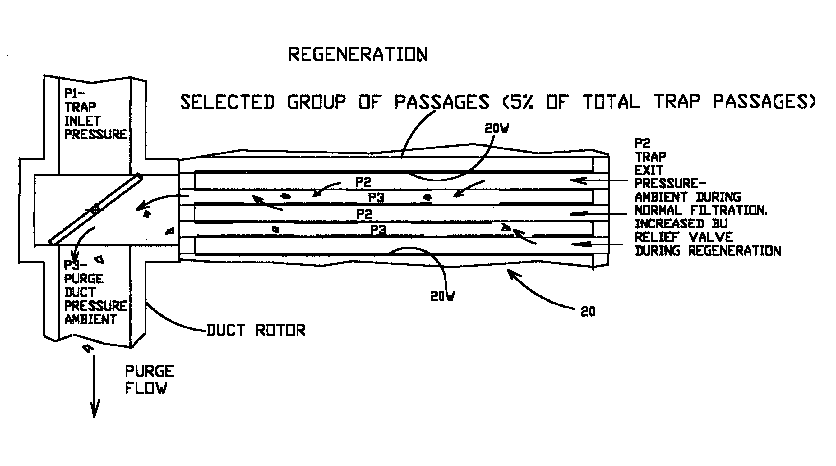
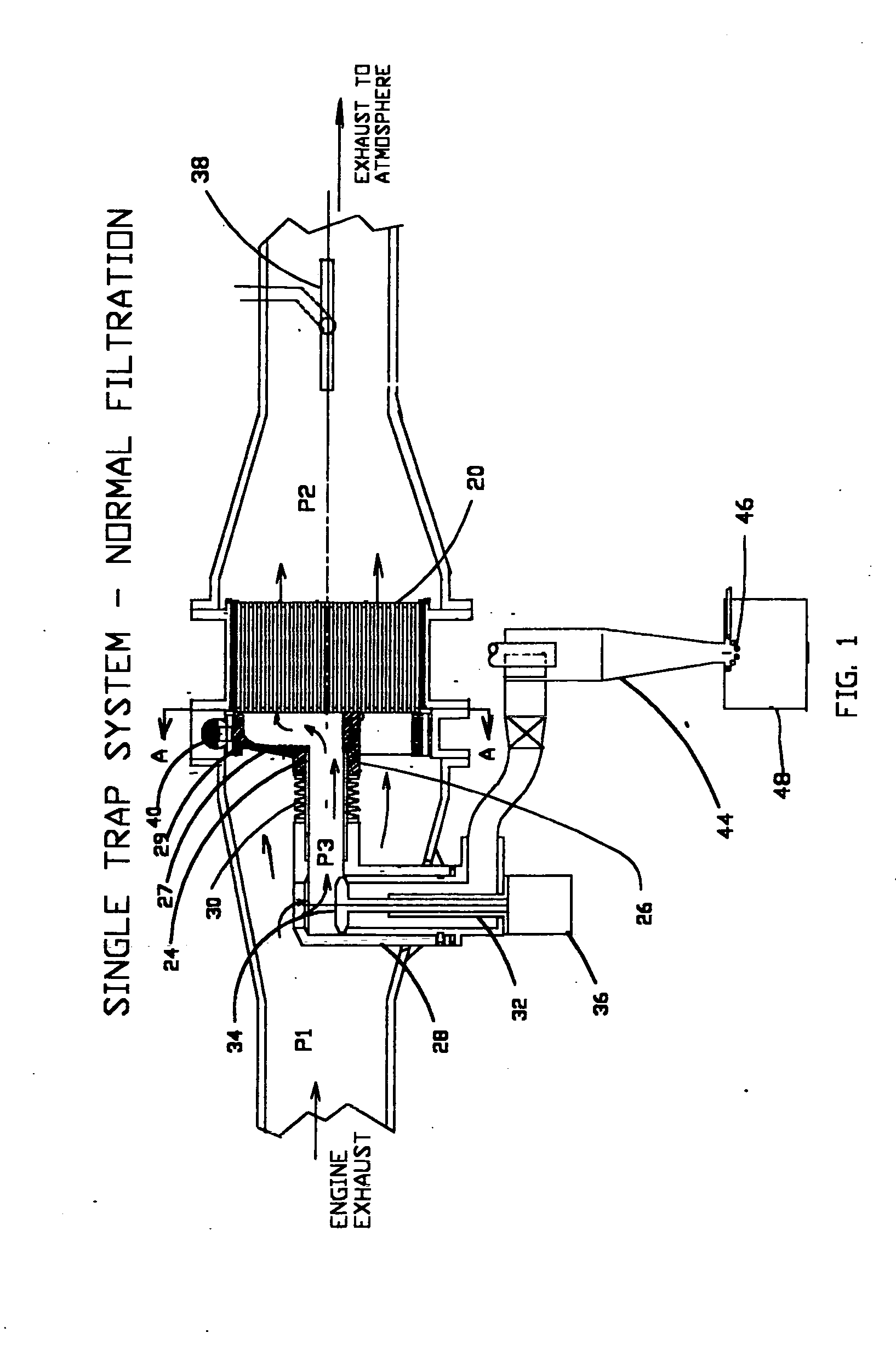
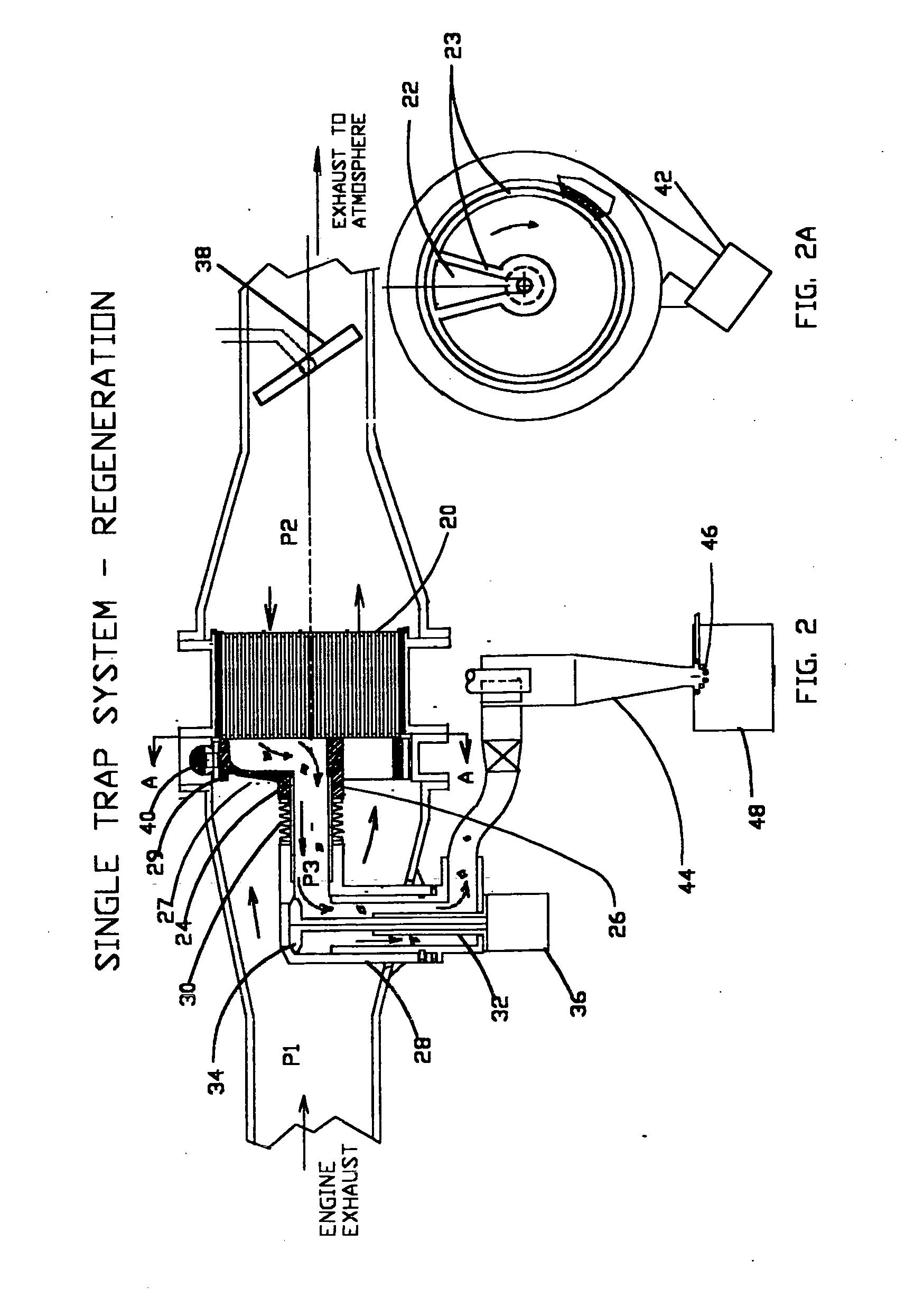
[0062]FIGS. 1 and 2 show the salient features of a particulate trap system with which various improvements are utilized. The principal parts are a monolithic wall-flow trap 20, a duct rotor 24, a duct rotor ratchet actuator 40, a mode valve assembly 32, a remotely actuated relief valve 38, and a cyclone separator 44, with its attached igniter 46 and ash storage chamber 48. The mode valve assembly 32 includes a purge duct 28, a two-position valve 34, and a mode valve actuator 36. The duct rotor 24 includes a duct section 27 and a ring gear 29, and is mounted loosely on a pilot bearing 26 which keeps the duct rotor centered. The duct rotor 24 is pressed against the face of the trap 20 by a spring / seal 30, with just enough force to preclude the duct rotor from moving off the face of the trap due to inertia or gas loading. The contact between the duc...


PUM

PropertyMeasurementUnit
pressureaaaaaaaaaa
pressureaaaaaaaaaa
reverse pressure dropsaaaaaaaaaa

Abstract

A particulate trap system for an exhaust system of an internal combustion engine includes a monolithic wall-flow particulate trap having a plurality of contiguous porous walls, and a remotely actuated relief valve downstream of said trap for periodically creating a reverse pressure throughout the exhaust system upstream of the relief valve and including said trap. A reversing apparatus periodically creates a reverse pressure drop across a portion of the contiguous porous walls of said trap to dislodge accumulated particulate and cause a portion of the filtered exhaust gas to flow back through said portion of the contiguous porous walls to remove particulate therefrom. A control system actuates the relief valve and the reversing apparatus. In one embodiment the system is utilized on a vehicle and the reversing apparatus includes a relief valve that is also operative as an exhaust break. Regeneration includes the steps of: creating a backpressure in the entire exhaust system from a location downstream of the trap; creating a reverse pressure drop across only a portion of the porous walls to dislodge accumulated particulate therefrom; and causing a portion of filtered exhaust gas to flow back through said portion of the porous walls to carry the dislodged particulate out of the trap.

Description

CROSS-REFERENCE TO RELATED APPLICATIONS[0001]This application claims the benefit of provisional patent application Ser. No. 60 / 734,164, filed 2005 Nov. 7 by the present inventor.[0002]This application also claims the benefit of provisional patent application Ser. No. 60 / 763,409, filed 2006 Jan. 30 by the present inventor.[0003]This application is a continuation-in-part of application Ser. No. 11 / 189,304 filed Jul. 26, 2005, which is a continuation of application Ser. No. 10 / 467,553 filed Aug. 1, 2003, and a continuation-in-part of application Ser. No. 10 / 846,780 filed May 14, 2004.FEDERALLY SPONSORED RESEARCH[0004]Not ApplicableSEQUENCE LISTING OR PROGRAM[0005]Not ApplicableFIELD OF THE INVENTION[0006]The present invention relates generally to methods and apparatus for removal of particulate from engine exhaust and more particularly to improved particulate filter systems, controls therefore, and a method of operatingBACKGROUND OF THE INVENTION[0007]The Environmental Protection Agenc...

Claims


Application Information

Patent Timeline
Patent Type & Authority Applications(United States)
IPC IPC(8): F01N3/023
CPCB01D53/944F01N13/017B01D2258/012F01N3/0222F01N3/0233F01N3/0235F01N3/0275F01N3/031F01N3/0821F01N3/0842F01N3/0885F01N3/2033F01N3/2828F01N3/38F01N11/00F01N2240/02F01N2240/06F01N2330/06F01N2510/06F01N2550/10F01N2550/12F01N2560/02Y02T10/26Y02T10/47B01D46/2418B01D46/0068B01D46/42B01D46/446B01D2279/30B01D53/96Y02A50/20Y02T10/12Y02T10/40B01D46/71
Inventor BAILEY, JOHN M.
Owner ILLINOIS VALLEY HLDG
Why Eureka
Try Eureka