Spark ignition and fuel injector system for an internal combustion engine

Inactive Publication Date: 2008-01-10
ADVANCED PROPULSION TECH
View PDF10 Cites 19 Cited by
  • Summary
  • Abstract
  • Description
  • Claims
  • Application Information

AI Technical Summary

Benefits of technology

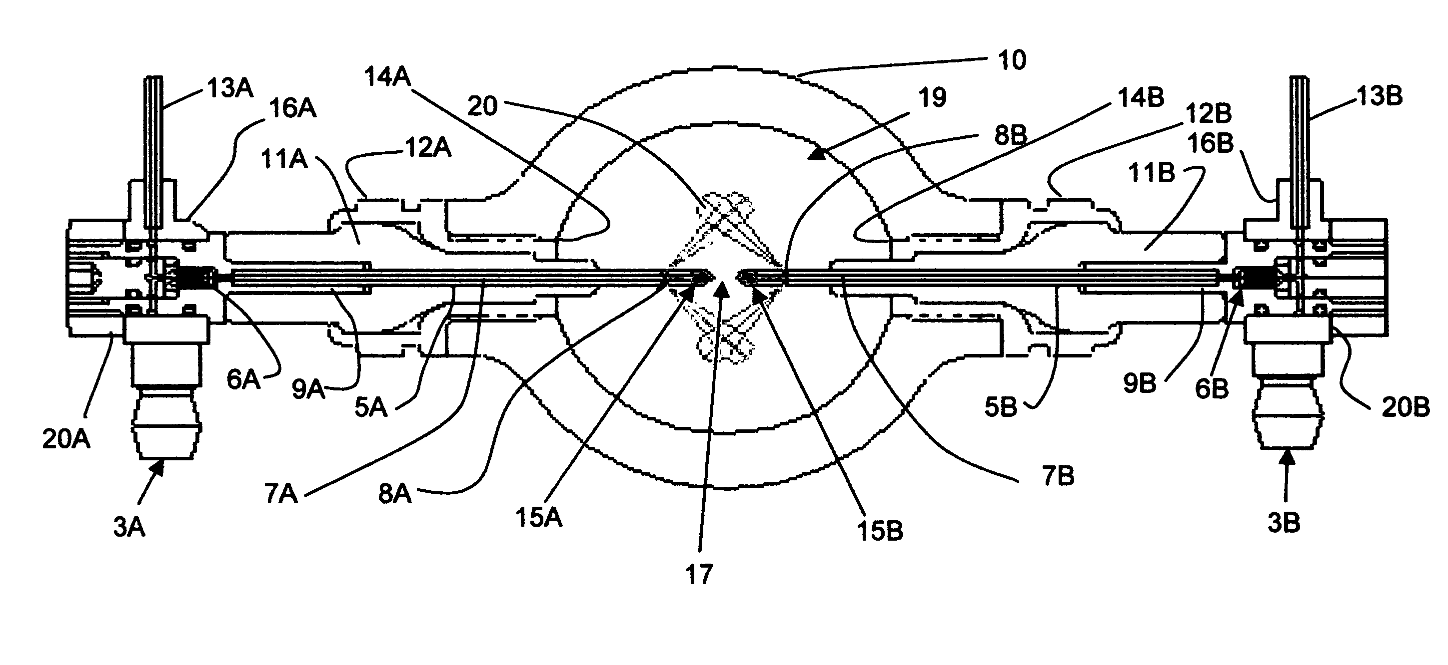
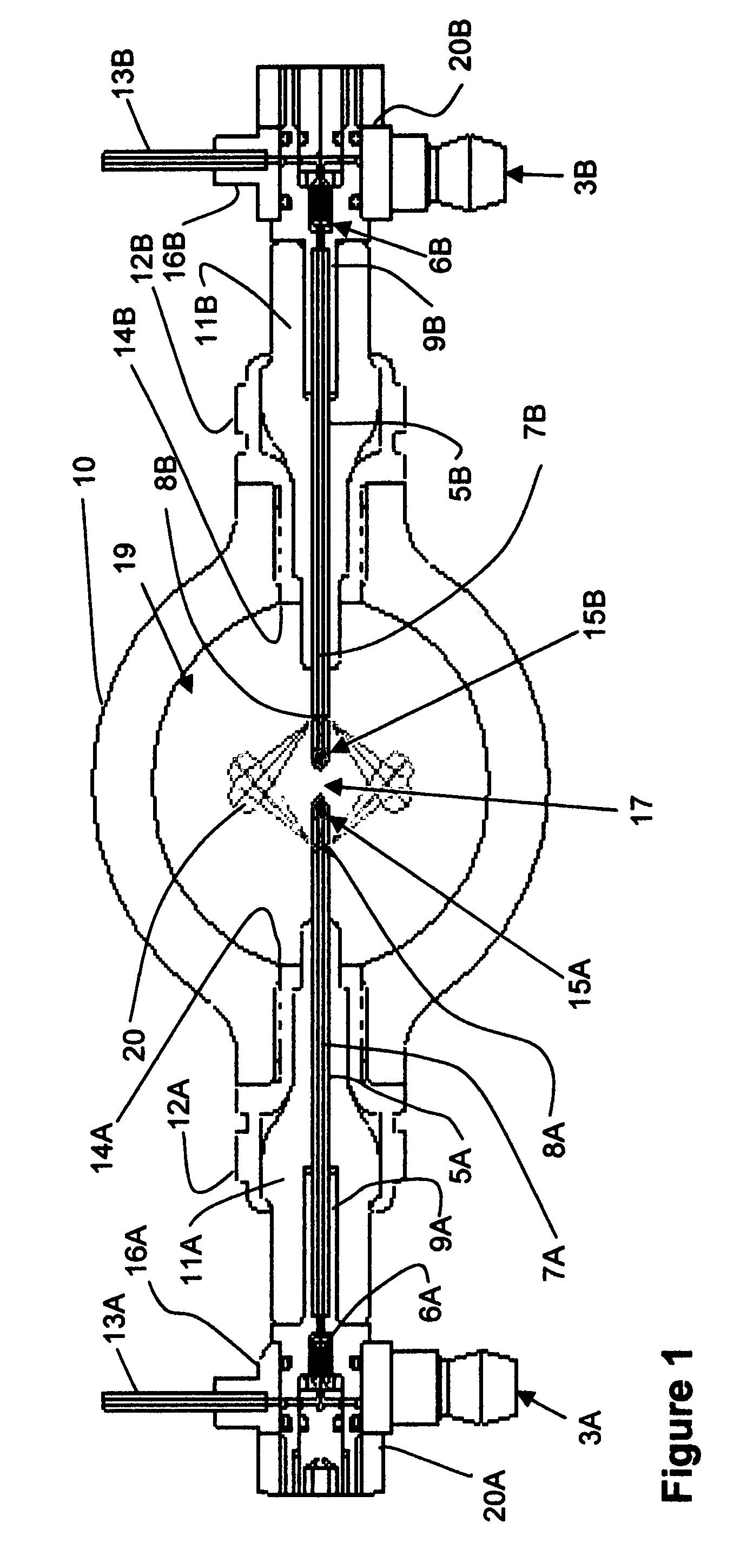
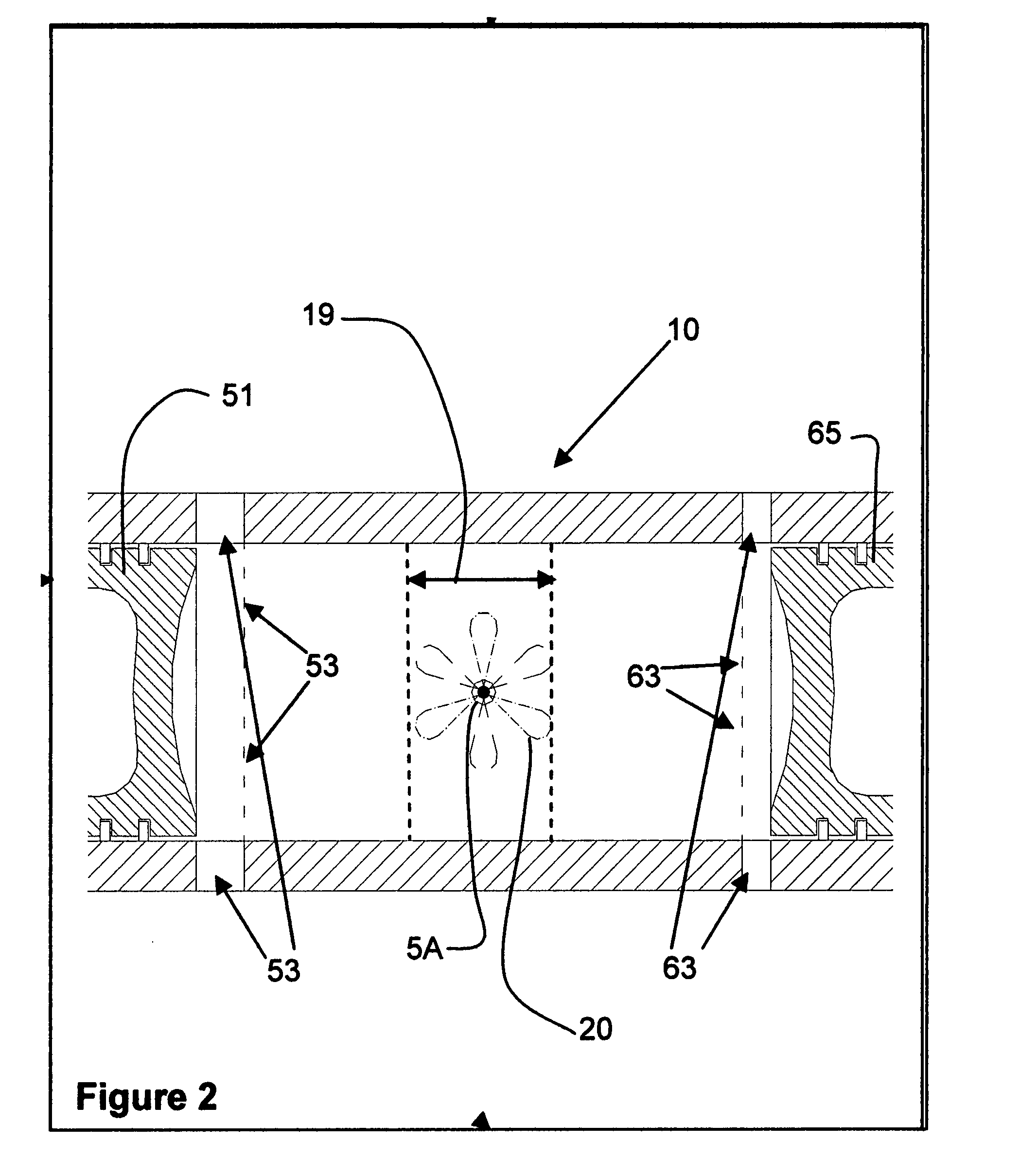
[0011]The present invention provides several key improvements to the ignition system of an internal combustion engine. A larger spark is produced because of the increased spacing and non-grounded relationship of the opposing electrodes, as well as the higher voltage potential available to be applied between the electrodes. The spark gap is located more central to the combustion chamber formed in the cylinder to improve ignition and combustion. Heat pr

Problems solved by technology

In such an engine that has no cylinder head, the mounting of a

Method used


Image

  • Spark ignition and fuel injector system for an internal combustion engine
  • Spark ignition and fuel injector system for an internal combustion engine
  • Spark ignition and fuel injector system for an internal combustion engine

Examples


Example

[0024]FIG. 4 is a schematic overview of the second embodiment of the fuel injector tube and spark electrode combination of the present invention. Ignition coil 100 provides positive and negative (ungrounded) electrical potential directly to opposing electrodes in the same cylinder. Since neither electrode is at ground potential, the electrical potential being applied across the spark gap is twice that applied to a conventional spark plug that sparks to ground. This allows for the gap to be much larger than is in a conventional spark plug and also a greater spark to be generated. In addition, the present invention creates an extremely long path to ground from each electrode tip and therefore eliminates the potential for current leakage within the combustion chamber.

[0025]A fuel tank 102 provides a fuel supply to the engine. Fuel pump 104 provides fuel under pressure to the fuel injectors via a fuel meter valve 106. Fuel meter valve 106 is controlled to determine the injection period ...


PUM


Abstract

An improved spark ignition system for an internal combustion engine that includes a pair of electrodes disposed to extend from opposite sides and into a combustion chamber to form a spark gap between them that is central to the combustion chamber. Each electrode is integral with a conductive fuel delivery tube that contains a capillary passage and fuel outlet ports adjacent the electrode. The heat from combustion conducted into the electrodes and fuel delivery tubes is used to vaporize the fuel within the capillary passages before it exits the outlet ports as an atomized fog into the combustion chamber adjacent the spark gap. The vaporization of the fuel flowing in the capillary passages absorbs energy from the electrodes and thus performs a cooling effect on the electrodes. The spacing of the electrodes from opposite sides of the cylinder also allows a design that can utilize and increased spark gap to produce a larger spark across the gap.

Description

RELATED APPLICATION[0001]This application claims benefit of U.S. provisional application Ser. No. 60 / 818,628 filed Jul. 5, 2006.TECHNICAL FIELD[0002]This invention is related to the field of internal combustion engines and more specifically to a spark ignition and fuel injection system utilized therein.BACKGROUND[0003]Conventional internal combustion engines are configured with spark plugs which contain two electrodes. A powered electrode is mounted within an insulator sleeve to have one end located within the cylinder. A ground electrode is configured to be opposed across an air gap with respect to the powered electrode. Such spark plugs are unitary in nature, since they contain both electrodes in a single unit.[0004]In some cases, spark plugs have been combined with fuel injectors to inject fuel through a nozzle into air gap portion of the spark plug. Such combinations also are unitary in nature since they contain the spark plug elements and fuel injector elements in a single unit...

Claims


Application Information

Patent Timeline
IPC IPC(8): F02M57/06
CPCF02M57/06
Inventor HOFBAUER, PETEREBBESON, BENGT EBBE OSKAR
Owner ADVANCED PROPULSION TECH
Why Eureka
Try Eureka