
Resonant combustion chamber and recycler for linear motors

a linear motor and recycler technology, applied in the direction of machines/engines, manufacturing tools, nailing tools, etc., can solve the problems of reducing scavenging efficiency, slow cycle times, and pre-combustion chambers can present problems, and achieve the effect of enhancing the free flow of scavenging air through both combustion chambers

Inactive Publication Date: 2005-04-05
ADAMS JOSEPH S
View PDF24 Cites 17 Cited by
  • Summary
  • Abstract
  • Description
  • Claims
  • Application Information

AI Technical Summary

Benefits of technology

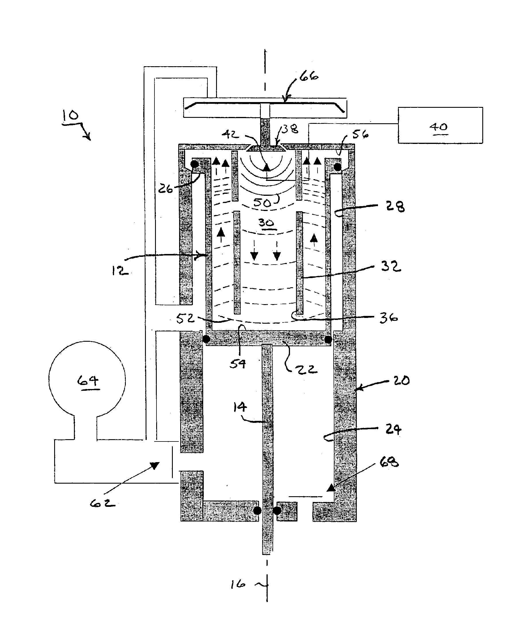
My invention contemplates improvements to scavenging efficiency and combustion efficiency. Accompanying the generation of an organized flame front within a combustion chamber is a faster moving compression wave. The combustion chamber can be arranged in accordance with my invention to exploit resonant properties of the compression wave for such purposes as compressing pre-established mixes of fuel and air and redirecting the flame front. A less restrictive scavenging path is possible for simplifying and enhancing scavenging and replenishing operations (i.e., recycling). Enhanced power output is possible by generating additional turbulence and compression within the combustion chamber.
For purposes of enhancing scavenging and recharging operations, the opening between the primary and secondary combustion chambers is preferably an unrestricted opening. However, the unrestricted opening is preferably a first of two openings between the primary and secondary combustion chambers. The unrestricted opening allows the compression wave to reflect from the secondary combustion chamber back into the primary combustion chamber in a direction opposed to a direction of propagation of the flame front within the primary combustion chamber. A second smaller of the two openings is positioned to inject the flame front into the secondary combustion chamber accompanying a collision with the reflected compression wave with the flame front within the primary combustion chamber. Four equally spaced openings are preferred for this purpose to accelerate combustion throughout the secondary combustion chamber. Thus, the returning compression wave effectively closes the unrestricted opening during ignition and forces the flame front through the smaller opening for accelerating combustion within the secondary combustion chamber. Following combustion, the unrestricted opening supports a free flow of scavenging and recharging gases between the primary and secondary combustion chambers.
The compression wave preferably propagates through an unrestricted opening between the primary and secondary combustion chambers. The reflected compression wave returns through the unrestricted opening and collides with the propagating flame front within the primary combustion chamber. The returning compression wave effectively closes the opening for compressing the unburned fuel and air in advance of the propagating flame front. The collision between the reflected compression wave and the propagating flame front forces a flame jet through one or more smaller openings between the primary and secondary combustion chambers for accelerating combustion of the mix of fuel and air in the secondary combustion chamber.
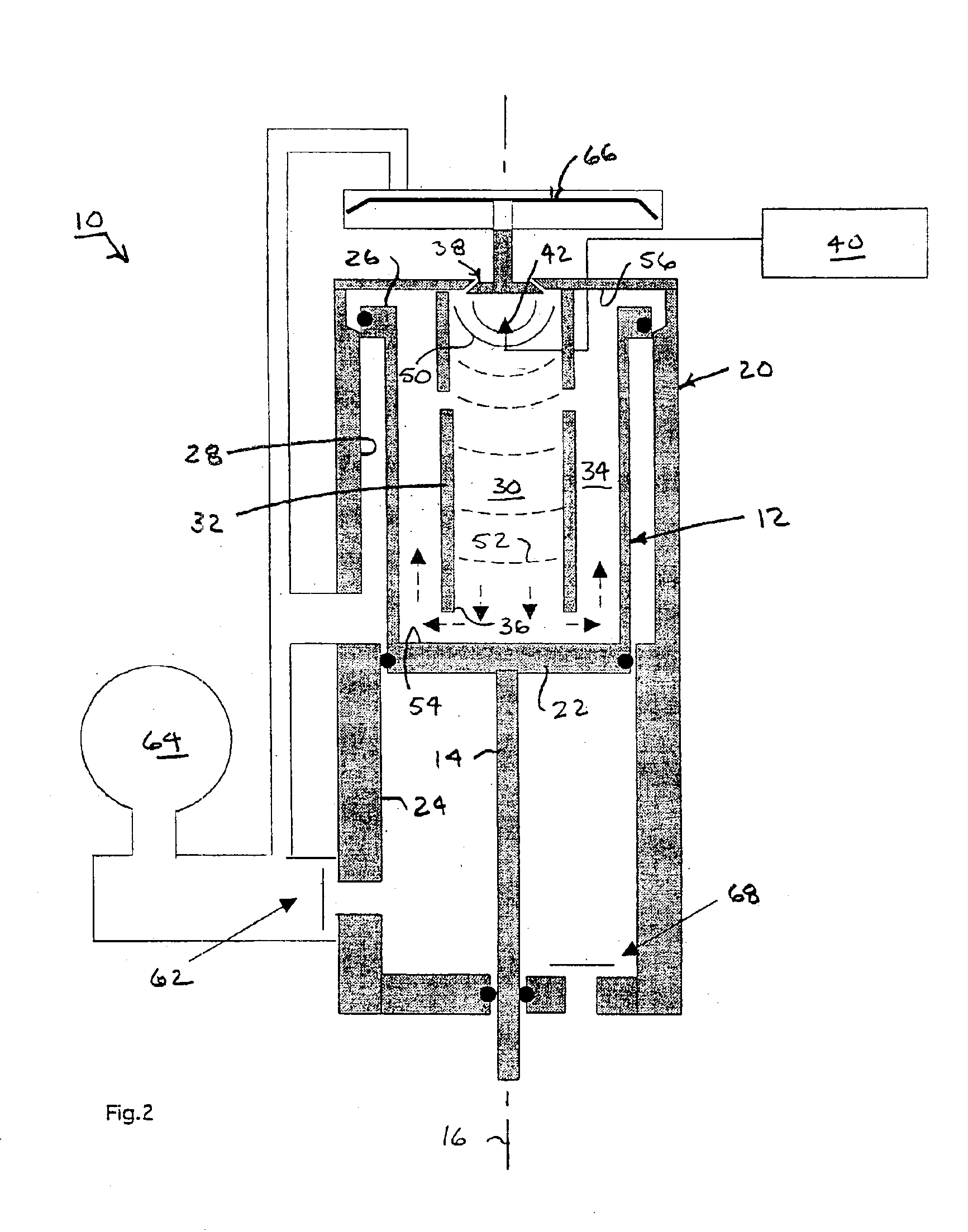
As the piston approaches the top of its stroke, a recess within the annular bore allows air from the plenum to flow into the secondary chamber. From there, the air flows through the unrestricted opening into the primary chamber and out the exhaust valve for scavenging combustion byproducts from both chambers. As air pressure in the plenum drops, the exhaust valve is closed, and fuel is injected into both combustion chambers for replenishing the combustible mix of fuel and air. The free flow of scavenging air through both combustion chambers is enhanced not only by the unrestricted opening between the chambers but also by a tubular form of both chambers that further supports flows through the chambers.

Problems solved by technology

Although increasing power output of spark-ignited linear motors, pre-combustion chambers can present a problem when the combustion chamber needs to be scavenged and the combusted gases replaced with a fresh fuel and air mix.
The restriction to scavenging and subsequent recharging flows can slow cycle times and reduce scavenging efficiency.

Method used


Image

  • Resonant combustion chamber and recycler for linear motors
  • Resonant combustion chamber and recycler for linear motors
  • Resonant combustion chamber and recycler for linear motors

Examples


Embodiment Construction

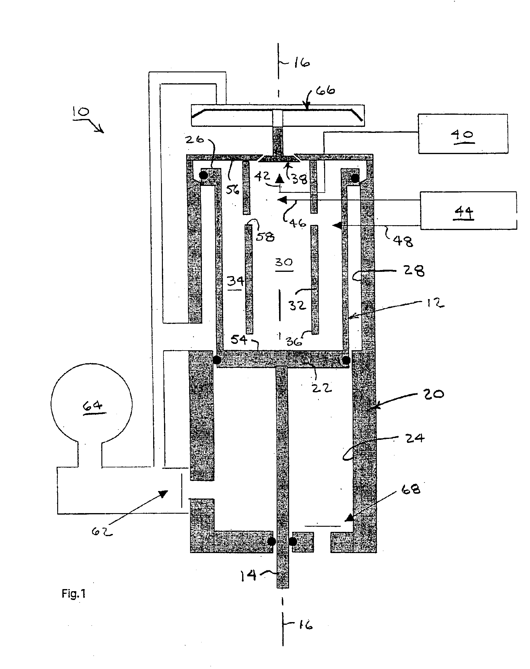
An exemplary spark-ignition combustion-powered linear motor 10 for a portable power tool is shown in progressive stages of operation throughout FIGS. 1-10. The motor 10 has a dual piston actuator 12 with a rod 14 for communicating the power to the portable tool (not shown). The piston actuator 12 is guided along a reference axis 16 within a cylinder housing 20. An inner concentric section 22 of the dual piston actuator 12 is guided within a central bore 24 of the cylinder housing 20, and an outer concentric section 26 of the dual piston actuator 12 is guided within a peripheral annular bore 28 of the cylinder housing 20.

A primary combustion chamber 30 occupies a cylindrical space within an open-ended tube 32. A secondary combustion chamber 34 occupies an annular space surrounding the open-ended tube 32. The primary and secondary combustion chambers 30 and 34 are arranged concentrically about the reference axis 16. An unrestricted opening 36 formed at one end of the open-ended tube 3...


PUM


Abstract

A combustion chamber system for a spark-ignited linear motor includes an open-ended primary combustion chamber located within a secondary combustion chamber. An unrestricted opening between the primary and secondary combustion chambers provides for more efficient scavenging of combustion byproducts. A compression wave trigged by a spark-ignited flame front within the primary combustion chamber is reflected within the secondary combustion. Upon return, the compression wave effectively closes the unrestricted opening of the primary combustion chamber by colliding with the flame front and forcing flame jets through smaller openings in the primary combustion chamber into the secondary combustion chamber for accelerating combustion within the secondary combustion chamber.

Description

TECHNICAL FIELDSpark-ignition combustion-powered linear motors provide on-board power for portable power tools and other devices such as nail guns, staplers, and other fastener driving tools.BACKGROUNDTypical spark-ignition linear motors of portable power tools operate at or near atmospheric pressure prior to ignition. A mixture of fuel and air is established in a combustion chamber and is ignited by a spark for combusting the mixture and driving a piston actuator of the tool. In order to achieve acceptable levels of efficiency from such motors, some sort of combustion accelerating device is added.For example, a portion of the charge (i.e., the mix of fuel and air) is held in a pre-combustion (or primary combustion) chamber and is ignited to build sufficient pressure to spew flame jets into the main combustion (or secondary combustion) chamber. The flame jets turbulate and ignite the pre-established mix of fuel and air in the main combustion chamber.My co-pending application Ser. No...

Claims


Application Information

Patent Timeline
IPC IPC(8): F02B71/00
CPCF02B71/00B25C1/08
Inventor ADAMS, JOSEPH S.
Owner ADAMS JOSEPH S
Learn More