Dc Current Sensor

Inactive Publication Date: 2008-03-06
ATS NETWORKS
View PDF0 Cites 21 Cited by
  • Summary
  • Abstract
  • Description
  • Claims
  • Application Information

AI Technical Summary

Benefits of technology

[0008] It is an object of the present invention to provide a DC current sensor capable of detecting DC current using a non-contact movement method of periodically reciprocating an upper part and a lower part of a divided magnetic core so that the pair of core parts repeatedly approach and retreat from one another in order to provide a simple structure and excellent current variation detection performance for small to large currents.
[0009] It is another object of the present invention to provide a DC current sensor capable of increasing the reliability of a measurement system by enabling adjustment of a measurement region or detection precision because electromotive force can be actively adjusted based on variation of the electromotive force at a constant current becoming larger as a range of movement of the magnetic core parts increases.
[0010] It is another object of the present invention to provide a DC current sensor capable of increasing the reliability of a measurement system by enabling adjustment of a measurement region or detection precision because electromotive force can be actively adjusted based on small-scale motion of an oscillator attached to spaced-apart magnetic core parts.
[0011] It is another object of the present invention to provide a DC current sensor capable of detecting current at low expense by disposing an oscillator and a magnetic thin layer adhered to each other on a plane to provide a miniaturized thin layer structure.
[0012] It is another object of the present invention to provide a DC current sensor capable of providing sufficient output through a simple amplifier circuit and being inexpensive to manufacture due to a good signal-to-noise ratio without a separate filter circuit.
[0021] Preferably, the DC current sensor can detect a wide range of DC current, from a small current of several milli Amps to a large current of several Amps, by adjusting the number of windings of the detection coil.

Problems solved by technology

However, it is difficult to precisely measure a small current of only several mA using the hall device alone.

Method used


Image

  • Dc Current Sensor
  • Dc Current Sensor
  • Dc Current Sensor

Examples


first embodiment

[0043] Hereinafter, the present invention will be described with reference to the accompanying drawings.

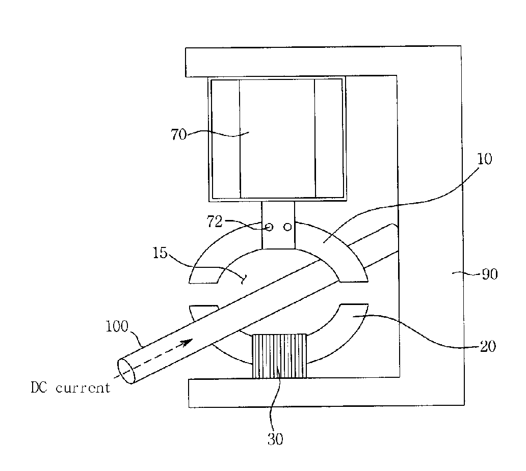
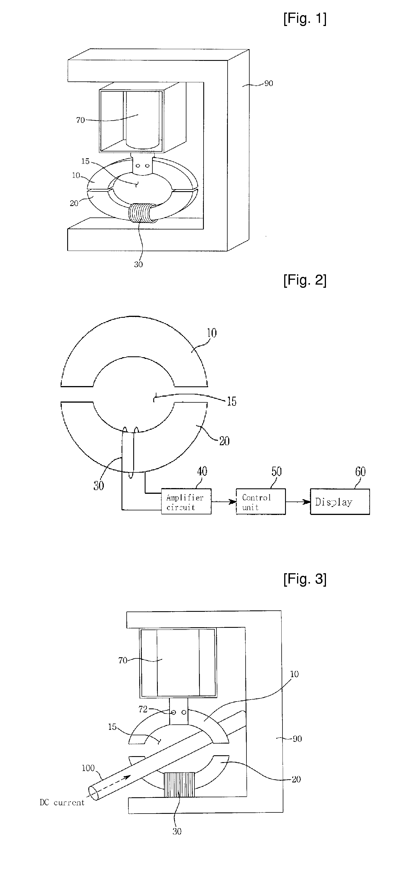
[0044]FIG. 1 illustrates a structure of a DC current sensor in accordance with a first embodiment of the present invention, FIG. 2 illustrates a DC current sensor in accordance with the first embodiment of the present invention, and FIG. 3 illustrates operation of a DC current sensor in accordance with the first embodiment of the present invention.

[0045] As shown in FIGS. 1 and 2, a DC current sensor in accordance with the present invention includes a magnetic core made of a soft magnetic material to form an annular shape (or a ring shape) having a space 15 in its center and symmetrically divided into an upper magnetic core part 10 and a lower magnetic core part 20. As a result, a pair of first gaps 140 are formed between the upper and lower magnetic core parts 10 and 20.

[0046] While the magnetic core parts 10 and 20 are preferably formed of Permalloy C (70% Ni-5 Mo-4 Cu-bal Fe)...

second embodiment

[0055] the present invention will now be described with reference to FIG. 4.

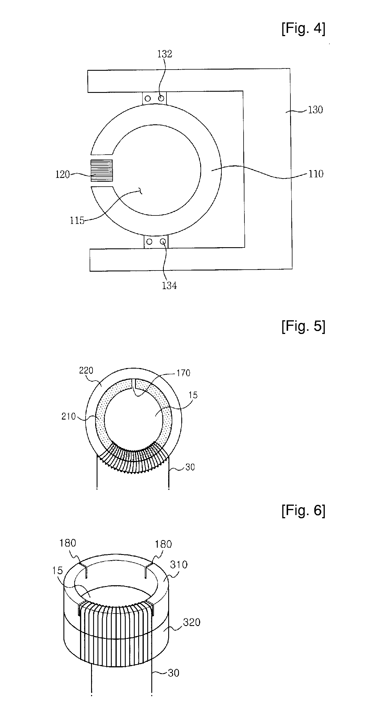
[0056]FIG. 4 illustrates a structure of a DC current sensor in accordance with a second embodiment of the present invention.

[0057] As shown in FIG. 4, the DC current sensor in accordance with a second embodiment of the present invention includes a magnetic core 110 having a second gap 160 at one side thereof. The magnetic core 110 is made of a soft magnetic material and has an annular shape (or a ring shape) having a center space 115. A detection coil 120 is installed at the second gap 160 of the magnetic core 110 to measure electromotive force generated by periodically reciprocating the detection coil so that it repeatedly approaches and retreats from the magnetic core 110. A signal processing circuit for producing a measurement value from current induced in the detection coil 120 is similar to that used in the system shown in FIG. 2.

[0058] An operating member (not shown) is installed at the detection coi...

third embodiment

[0061] the present invention will now be described with reference to FIG. 5.

[0062]FIG. 5 illustrates a structure of a DC current sensor in accordance with a third embodiment of the present invention.

[0063] As shown in FIG. 5, the DC current sensor in accordance with a third embodiment of the present invention includes a magnetic core 210 having a third gap 170 at one side thereof, and a piezo-electric oscillator 220 installed around an outer periphery of the magnetic core 210.

[0064] That is, the DC current sensor in accordance with the third embodiment has a structure in which the piezo-electric oscillator 220 and the magnetic core 210 are adhered to each other, and the third gap 170 is formed at one side of the magnetic core 210.

[0065] However, the arrangement of the magnetic core 210 and the piezo-electric oscillator 220 is not limited to the structure of FIG. 5; alternatively, the magnetic core 210 may be disposed around an outer periphery of the piezo-electric oscillator 220....


PUM


Abstract

Disclosed is a DC current sensor including: a magnetic core symmetrically divided into two parts and having a center space through which a conductive wire carrying DC current to be measured passes; a detection coil wound around one of the magnetic core parts for measuring electromotive force; an operating member installed at the other one of the magnetic core parts repeatedly approach and retreat the magnetic core parts from each other in a non-contact manner; and a controller for controlling the operating member to repeatedly approach and retreat the magnetic core parts from each other to generate electromotive force on a magnetic circuit, wherein there are a pair of gaps between the pair of magnetic core parts, and the generated electromotive force is measured by the detection coil and output from an amplifier circuit to detect the DC current flowing through the conductive wire. Therefore, it is possible to increase detection precision of the DC current sensor by finely controlling the size of the gap.

Description

TECHNICAL FIELD [0001] The present invention relates to a DC current sensor, and more particularly, to a DC current sensor capable of measuring electromotive force generated by moving a magnetic core having a gap in a non-contact manner to thereby detect DC current. BACKGROUND ART [0002] Recently, as devices including an inverter for using DC current, such as electric appliances, electric automobiles, and so on, increase in number, the need for a sensor for detecting a load on a DC motor installed in various devices to perform required control functions, or a DC current sensor used in a DC current interrupter, is increasing. [0003] Some well known types of such a DC current sensor are a magnetic amplifier type, a magnetic multi-vibrator type, a hall device type, and so on. [0004] The hall device type sensor is based on a magnetic resistance effect in which a voltage is output in proportion to magnetic flux by disposing a hall device between ferrite or permalloy-based magnetic core p...

Claims


Application Information

Patent Timeline
IPC IPC(8): G01R33/06G01R19/165
CPCG01R19/16509G01R19/165
Inventor KIM, HYUN-WOOK
Owner ATS NETWORKS
Why Eureka
Try Eureka