
Method and apparatus for merging call components during call reconstruction

a call component and call reconstruction technology, applied in data switching networks, instruments, frequency-division multiplexes, etc., can solve problems such as low reliability, low efficiency, and high cost of redundant databases, and achieve efficient and rapid matching of various components, and less resources

Active Publication Date: 2008-02-28
AVAYA INC
View PDF59 Cites 5 Cited by
  • Summary
  • Abstract
  • Description
  • Claims
  • Application Information

AI Technical Summary

Benefits of technology

The present invention is about a system that helps to reconstruct communication between two or more parties in case of a failure in the primary communication server. The system maintains communication state information on a communication node, such as a media gateway or communication terminal. This information includes details about call set-up, tear down, address translation, call appearances for each party, feature selections, and billing information. The system uses unique identifiers for each communication to help in reconstructing the communication. This helps to efficiently and quickly match the various components of the communication and ensures that the reconstructed communication is identical to the original communication. The system uses low bit numeric, alphabetical, or alphanumeric sequences as identifiers, which require fewer resources to store and manage. Overall, the invention provides a reliable and efficient solution for communication reconstruction during failures.

Problems solved by technology

However, establishing a common, redundant database can be expensive.
In addition, such databases can create a data bottleneck, especially when a large number of servers are accessing the database.
Furthermore, such a solution is not very robust, as network failures can prevent call controllers from accessing the common database.
However, this approach adds overhead and complexity, particularly as the number of communication servers available on a system increases.
This can result in network congestion.
In addition, the solution is not very robust, as network failures can prevent servers from communicating with one another.
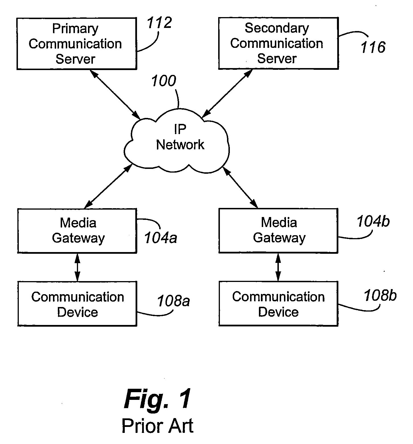
However, where a call spans multiple gateways (or includes one or more inter-gateway connections (which commonly is an IP-bearer connection between two gateways on a common or shared primary communication server)), such as a call between communication devices 108a and b (which spans gateways 104a and b), a naive call reconstruction algorithm would, as the call components migrate, reconstruct the part of the call handled by each gateway as a separate or new call, which, as noted above, can cause some features to be lost to the communicants.

Method used


Image

  • Method and apparatus for merging call components during call reconstruction
  • Method and apparatus for merging call components during call reconstruction
  • Method and apparatus for merging call components during call reconstruction

Examples


Embodiment Construction

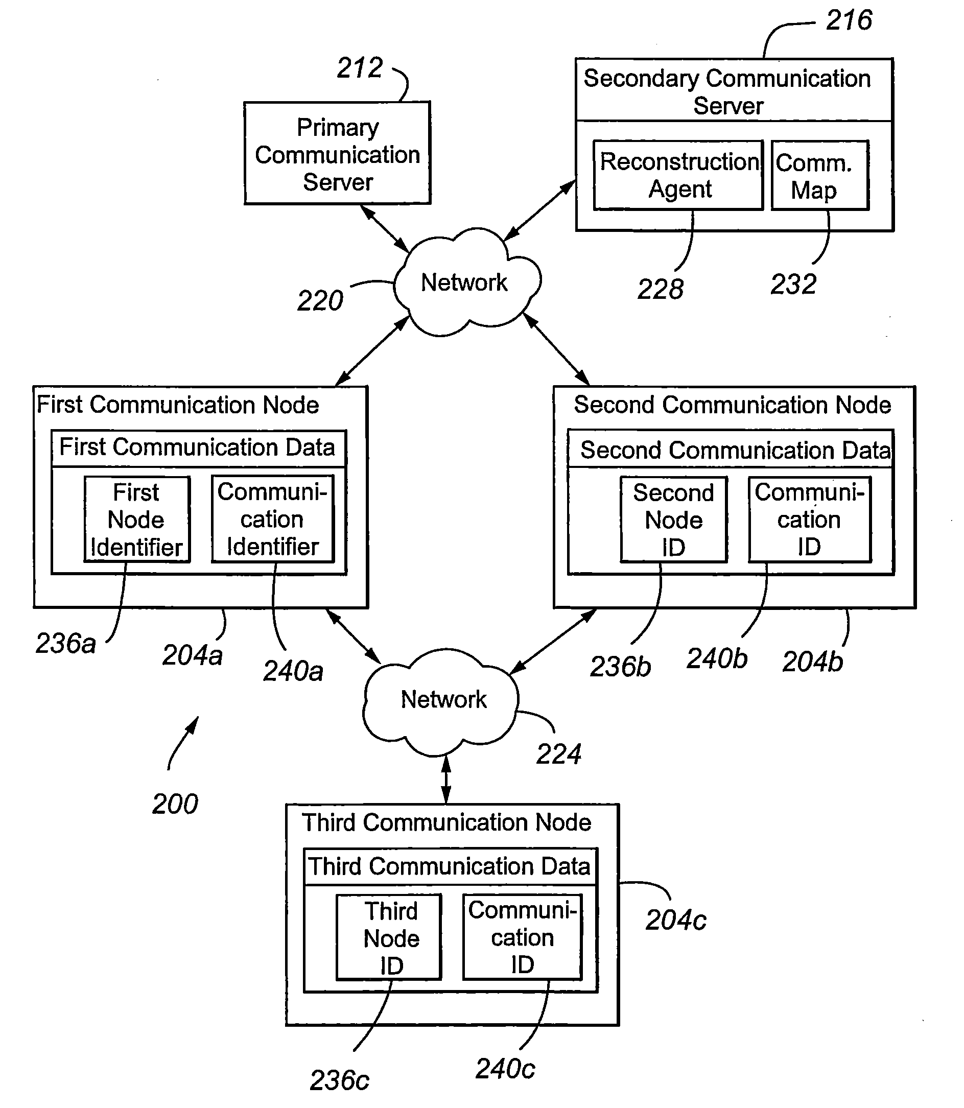
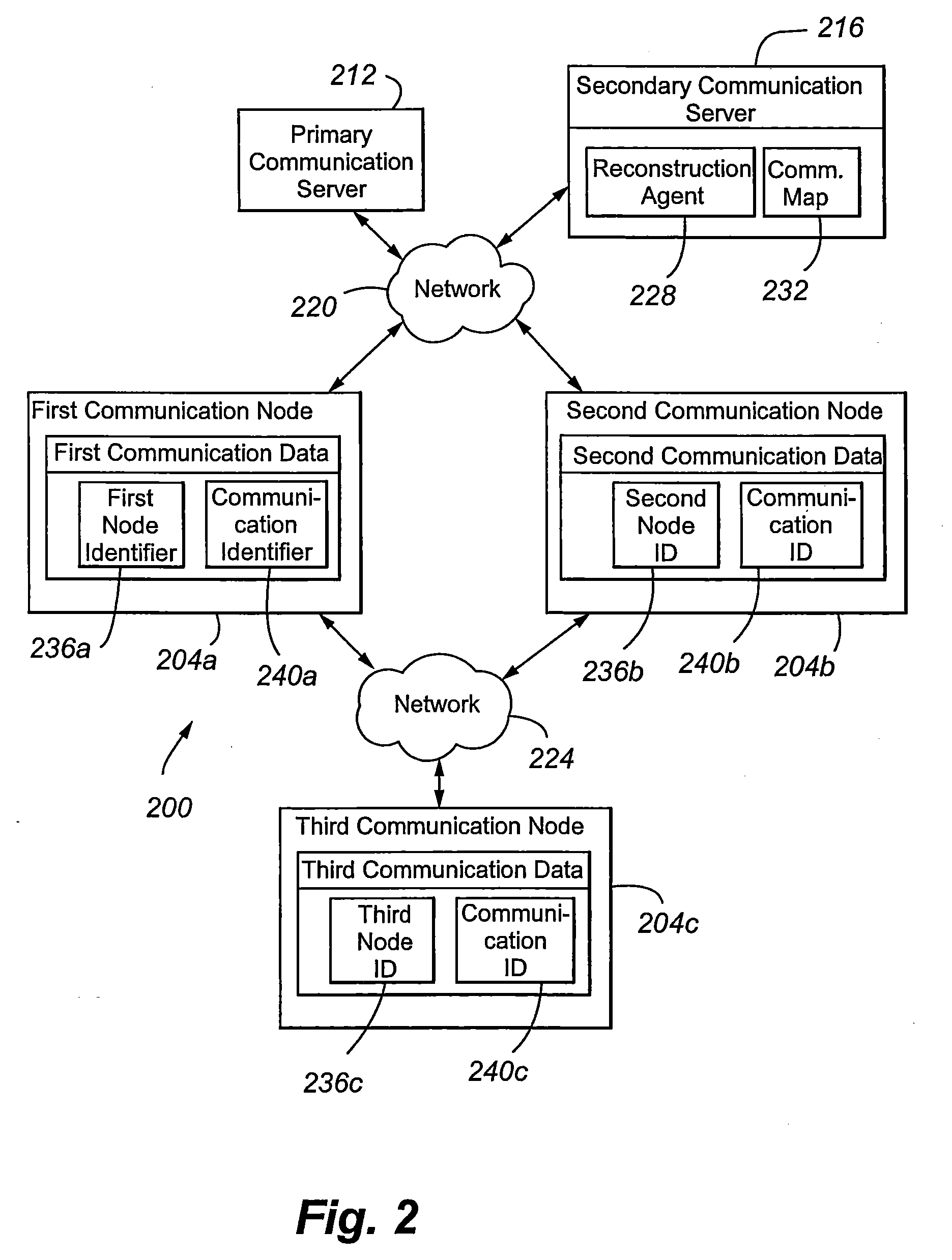
[0019] With reference now to FIG. 2, a realtime or near realtime communication arrangement 200 in accordance with an embodiment of the present invention is illustrated. In general, the communication arrangement 200 involves a number of communication nodes 204a-c interconnected to one another by communication networks 220 and 224. The communication nodes are further in communication, via the networks 220 and 224, with a primary and secondary communication servers 212 and 216.

[0020] The communication nodes 204a-c can be any terminating or intermediate node. For example, the nodes can represent one or more of a gateway, port network, center stage switch, and a communication terminal, such as a wired or wireless circuit-switched or packet-switched telephone (e.g., an IP soft phone or hard phone, a Digital Signal Processor or DSP telephone, a video phone, a Personal Digital Assistant, a computer running an instant messaging application, and the like). In a preferred embodiment, the firs...


PUM


Abstract

The present invention is directed to a secondary communication server 216 for assuming control of a communication formerly controlled by a primary communication server 212 in the event of a failure, comprising: (a) an input operable to (i) receive, from a first communication node 204a, first communication information, wherein the first communication information is associated with the communication and comprises a first node identifier 236a and / or a communication identifier 240a, the first node identifier 236a is associated with a second communication node 204b, the communication identifier is associated with the communication, and the second communication node 204b comprises second communication information associated with the communication and (ii) thereafter receive, from the second communication node 204b, the second communication information; and (b) a reconstruction agent 228 operable to identify the second communication information based on the first node identifier 236a and / or communication identifier 240a.

Description

CROSS REFERENCE TO RELATED APPLICATION [0001] This application claims the benefits under 35 U.S.C. § 119 of U.S. Provisional Patent Application Ser. No. 60 / 615,295, filed Sep. 30, 2004, of the same title and to the same inventors, which is incorporated herein by this reference. [0002] Cross reference is made to U.S. patent application Ser. No. 10 / 676,659, filed Sep. 30, 2003, entitled “METHOD AND APPARATUS FOR MIGRATING TO AN ALTERNATE CALL CONTROLLER”, which is incorporated herein by this reference.FIELD OF THE INVENTION [0003] The present invention is directed to realtime data transmission over a network. In particular, the present invention is directed to maintaining call state information when migrating between call controllers. BACKGROUND OF THE INVENTION [0004] Packet data networks are increasingly used for the exchange of realtime audio, video and data communications. Various protocols, including the H.323 protocol, require the establishment of a call signaling channel that i...

Claims


Application Information

Patent Timeline
Patent Type & Authority Applications(United States)
IPC IPC(8): H04L12/66H04L69/40
CPCH04L29/06027H04L69/40H04L65/1083H04L65/1043H04L65/1101
Inventor GILLESPIE, DONALD E.MARWAH, MANISHVELAMALA, VIVEKANANDA
Owner AVAYA INC
Learn More