Contact for an electrical connector

Inactive Publication Date: 2008-02-28
HON HAI PRECISION IND CO LTD
View PDF23 Cites 5 Cited by
  • Summary
  • Abstract
  • Description
  • Claims
  • Application Information

AI Technical Summary

Benefits of technology

[0006]A stamped contact for an electrical connector is provided according to one embodiment of the present invention. The stamped contact is formed from a sheet of conductive terminal, and includes a middle spring piece residing within a passage of a connector body, a contact portion on a distal region of the middle spring piece for engaging a mating conductive element, and a side spring piece extending downwardly from the contact portion. Retention structure is

Problems solved by technology

Failure of a single conductive contact to make a re

Method used


Image

  • Contact for an electrical connector
  • Contact for an electrical connector
  • Contact for an electrical connector

Examples


Embodiment Construction

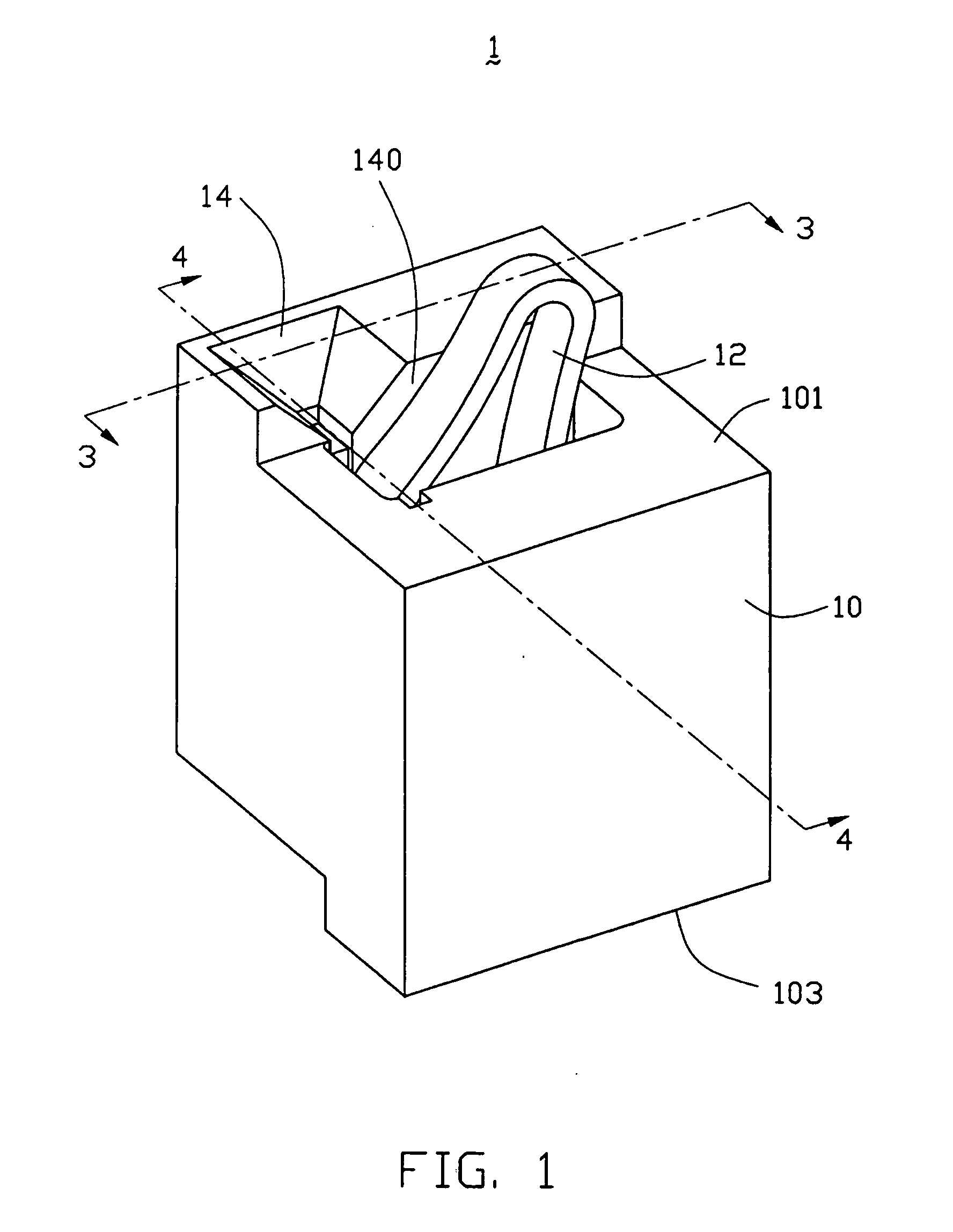
[0017]Referring to FIGS. 1, 3 and 4, an electrical connector 1 according to the first embodiment of the present invention is shown to include an insulative housing or connector body 10, and a plurality of conductive contacts 12 resided within the insulative housing 10. For the illustration purpose, merely a part of the electrical connector 1 is included. The insulative housing 10 defines a mating side 101 adapted to mate with a mating electrical member or component, such as an IC package (not shown, as known in the prior art), and an opposite mounting side 103 adapted to face an electrical member, such as a substrate (not shown, as known in the prior art), and includes a plurality of passages 14 extending from the mating side 101 towards the mounting side 103 through the insulative housing 10.

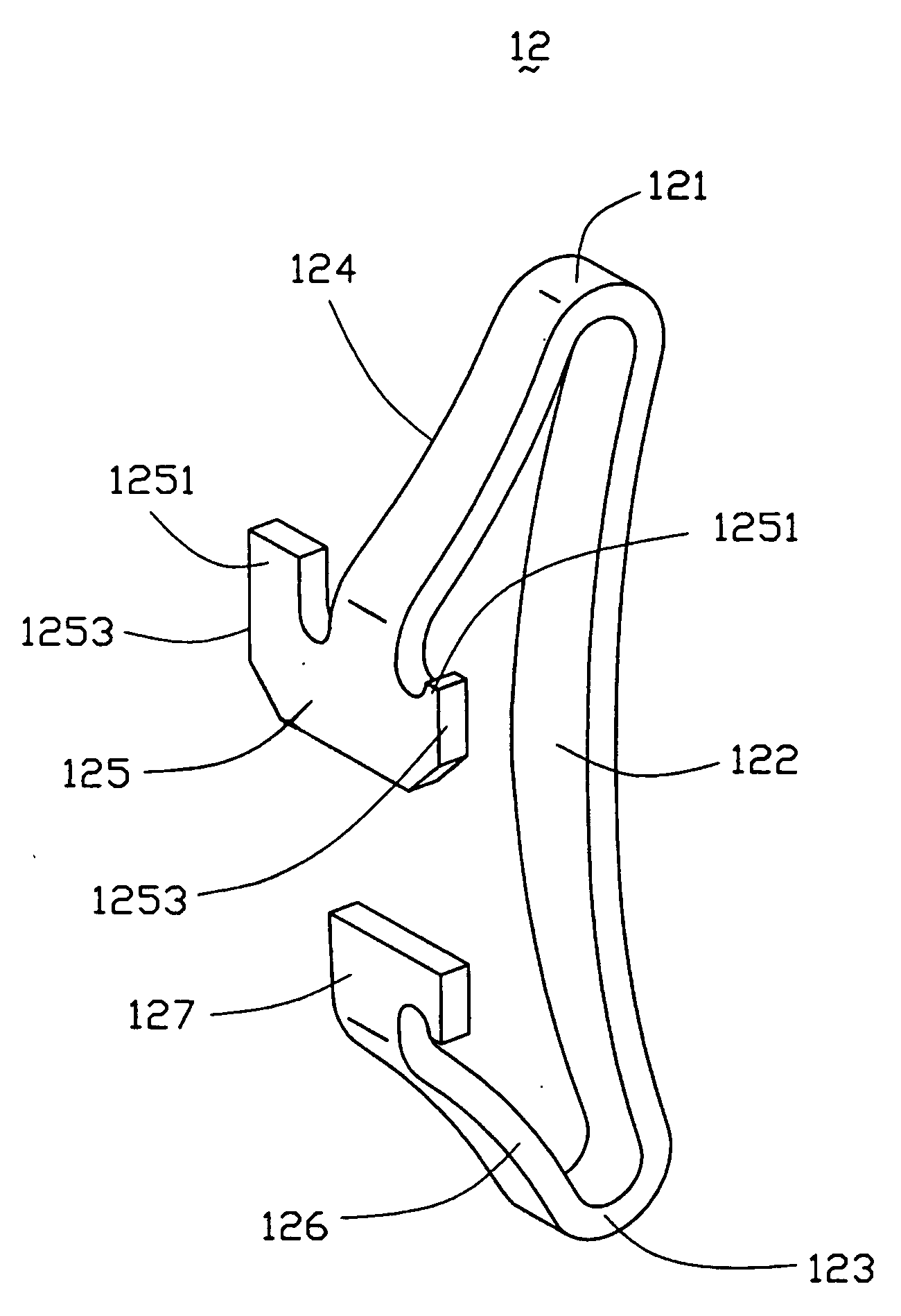
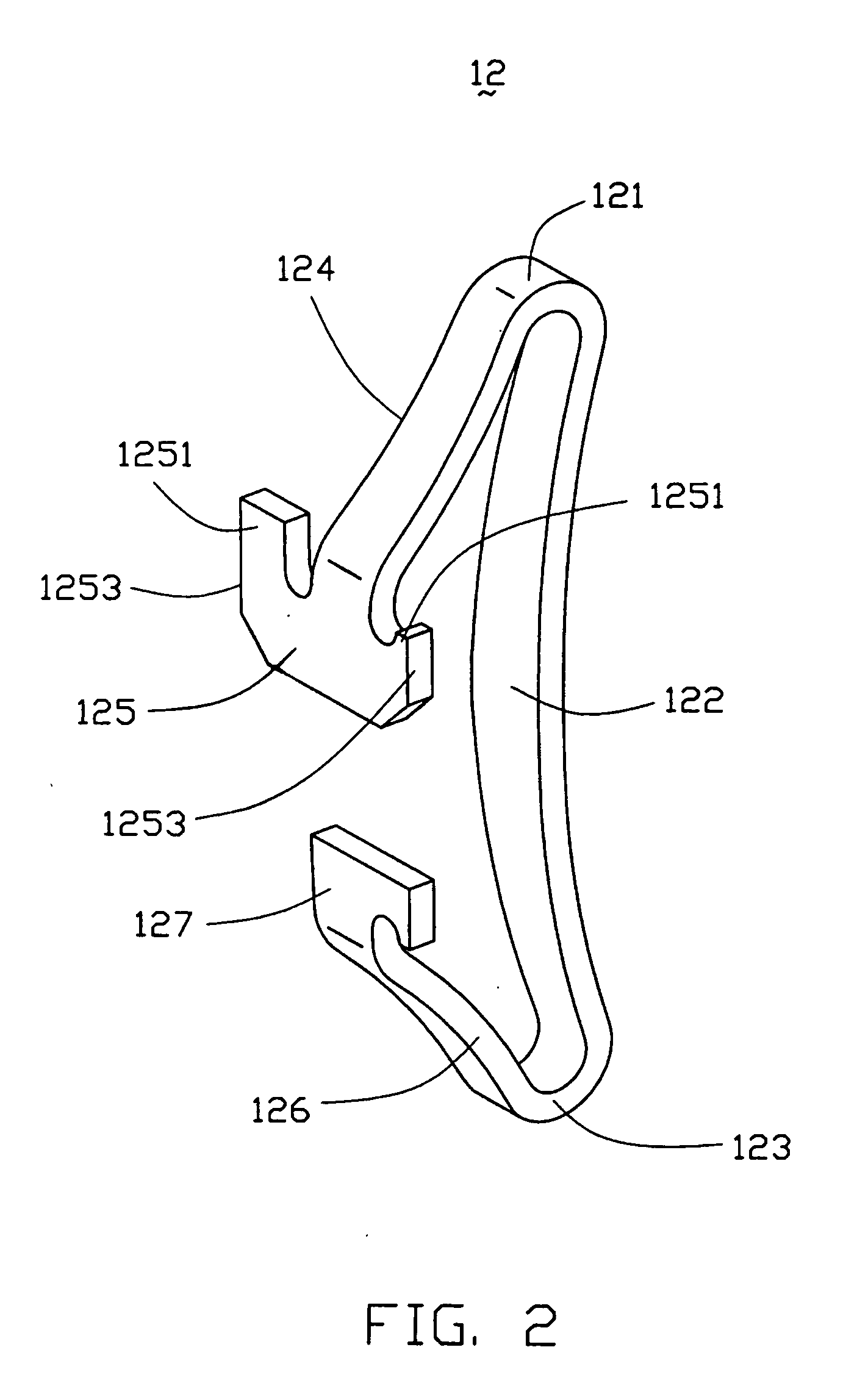
[0018]Referring to FIG. 2, the conductive contact 12 is stamped from a single sheet of conductive material. The conductive contact 12 includes a middle spring beam or piece 122 resided within o...


PUM


Abstract

An electrical connector (1) includes an insulative housing (10) and a plurality of stamped contacts (12) resided therewithin. The conductive contact includes a central spring beam (122), a side spring beam (124) located at one side of the central spring beam, and a contact portion (121) formed between the central spring beam and the side spring beam for electrically mating with a mating component. The central spring beam extends inwardly of the contact portion and towards an end portion of the side spring beam. Such a configuration of the central spring beam will ensure that the conductive contact has a predetermined robustness thereof while possessing the required spring properties for the stamped contact.

Description

BACKGROUND OF THE INVENTION[0001]1. Field of the Invention[0002]The present invention relates to the art of electrical connectors, and more particularly to a stamped contact for use in an electrical connector.[0003]2. General Background[0004]Electrical connectors are used for forming electrical connections between spaced contact pads on adjacent parallel circuit members, such as an IC package and a substrate. The electrical connector typically includes an insulative housing and a plurality of conductive contacts resided within the insulative housing. The conductive contacts extend towards top and bottom sides of the insulative housing in order to establish the electrical connection between the aligned pairs of contact pads through the electrical connector sandwiched between the two parallel members. Making good and reliable electrical connections between the pads of the two members typically requires the conductive contact to have a robust capability so as to withstand a normal forc...

Claims


Application Information

Patent Timeline
IPC IPC(8): H01R12/00
CPCH01R12/714H01R13/2435
Inventor POLNYI, IGOR
Owner HON HAI PRECISION IND CO LTD
Why Eureka
Try Eureka