
Electrical device

a technology of electric devices and connecting regions, applied in the direction of coupling device connections, testing electric installations on transport, instruments, etc., can solve the problems of high material stress in the connecting region between the main conductors, and achieve the effect of improving the manufacture of both conductor sections as such, and the force transmission point between the second conductor and the attachment poin

Inactive Publication Date: 2008-02-28
ROBERT BOSCH GMBH
View PDF36 Cites 9 Cited by
  • Summary
  • Abstract
  • Description
  • Claims
  • Application Information

AI Technical Summary

Benefits of technology

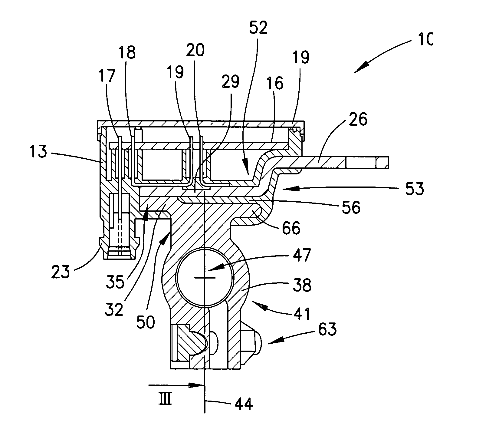
[0003] The electrical device according to the present invention, in particular a device for determining electrical variables, such as a battery sensor, for example, has the advantage that space is provided for affixing an additional attachment point which thus greatly reduces the torque load in the connecting region between the attachment point and the conductors. The service life is thus improved.
[0004] If on the other side of the central axis viewed from the interface an additional connecting region is present, which connects one of the conductor sections to the attachment point, the attachment, in particular of the second conductor, and thus the torque load in the interface, is greatly reduced.
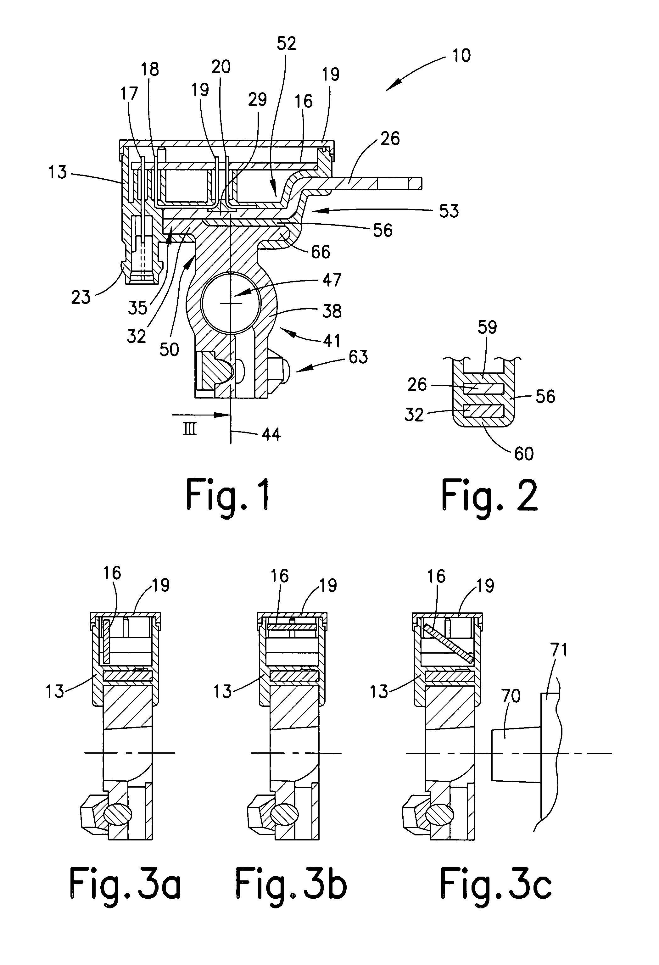
[0005] One simple possibility for connecting the second conductor section to the attachment point is to select a form fit. This is the case in particular when the form fit is provided by a molded part which encloses two conductor sections, namely, the first and the second conductor sections. It is advantageous when the molded part has the shape of two closed interconnected rings (figure eight shape). The transmittable restraining forces are particularly high. Secure insulation between the two conductor sections also results when the connection point at which the two rings are joined insulates the two conductor sections from each other.
[0007] If the first and second conductor sections are connected to one another at the interface, i.e., integrally joined, the ease of manufacture of both conductor sections as such, and also of the force transmission points between the second conductor and the attachment point, is improved.

Problems solved by technology

In such a design it is disadvantageous that vibrational loads or tensile loads on the main conductor may result in high material stresses in the connecting region between the main conductor and the terminal.

Method used


Image

  • Electrical device
  • Electrical device

Examples


Embodiment Construction

[0011]FIG. 1 shows a longitudinal section of electrical device 10. The electrical device includes a housing 13 in which a printed circuit board 16 is situated. Housing 13 is closed by a cover 19. Housing 13 is made of plastic, and is manufactured by injection molding. The material of this housing 13 includes objects that may be different such as, for example, various pins 17, 18, 19, and 20. Pin 17 allows a connection to the enclosure for housing 13, and is a part of a plug 23. Pins 18, 19, and 20 are connected to a conductor, in this case referred to as second conductor section 26. The so-called battery current flowing through second conductor section 26 may be determined with the aid of these pins 18, 19, and 20. For this purpose, second conductor section 26 has a so-called shunt section 29. Pins 19 and 20 enclose shunt section 29, which has the usual characteristic of having a particularly constant resistance under various operating conditions. This characteristic allows the volt...


PUM


Abstract

An electrical device, in particular a device for determining electrical variables (battery sensor), is provided which includes a connecting region between the part of the device which determines electrical variables and an attachment point. The connecting region has an essentially central axis. The device has a conductive interface between two conductor sections, the interface being offset from the central axis.

Description

FIELD OF THE INVENTION [0001] The present invention relates to an electrical device, in particular a device for determining electrical variables. BACKGROUND INFORMATION [0002] Unexamined German Patent Application No. 10 2004 049 153 is cited as an example thereof. In such a design it is disadvantageous that vibrational loads or tensile loads on the main conductor may result in high material stresses in the connecting region between the main conductor and the terminal. SUMMARY OF THE INVENTION [0003] The electrical device according to the present invention, in particular a device for determining electrical variables, such as a battery sensor, for example, has the advantage that space is provided for affixing an additional attachment point which thus greatly reduces the torque load in the connecting region between the attachment point and the conductors. The service life is thus improved. [0004] If on the other side of the central axis viewed from the interface an additional connectin...

Claims


Application Information

Patent Timeline
Patent Type & Authority Applications(United States)
IPC IPC(8): H01R4/00
CPCG01R1/203G01R31/006H01R13/6683G01R31/3696H01R11/287G01R31/3606G01R31/364G01R31/382
Inventor KOELLE, GERHARDMAZINGUE-DESAILLY, STEPHANLERICH, ALEXANDERHELLWIG, ROLAND
Owner ROBERT BOSCH GMBH
Learn More