Stirrup-Type Power Utility Electrical Connector Assemblies

Inactive Publication Date: 2008-02-28
TYCO ELECTRONICS CANADA +1
View PDF26 Cites 23 Cited by
  • Summary
  • Abstract
  • Description
  • Claims
  • Application Information

AI Technical Summary

Benefits of technology

[0008] It would be desirable to provide a lower cost, more universally applicable alternative to conventi

Problems solved by technology

Such bolt-on connectors have been widely accepted in the industry primarily due to their ease of installation, but such connectors are not without disadvantages.
Applicable torque requirements, however, may or may not be actually achieved in the field and even if the bolt is properly tightened to the proper torque requirements initially, over time, and because of relative movement of the conductors relative to the connector pieces or compressible deformation of the cables and/or the connector pieces over time, the effective clamping force may be considerably reduced.
Additionally, the force produced in the bolt is dependent upon frictiona

Method used


Image

  • Stirrup-Type Power Utility Electrical Connector Assemblies
  • Stirrup-Type Power Utility Electrical Connector Assemblies
  • Stirrup-Type Power Utility Electrical Connector Assemblies

Examples


Example

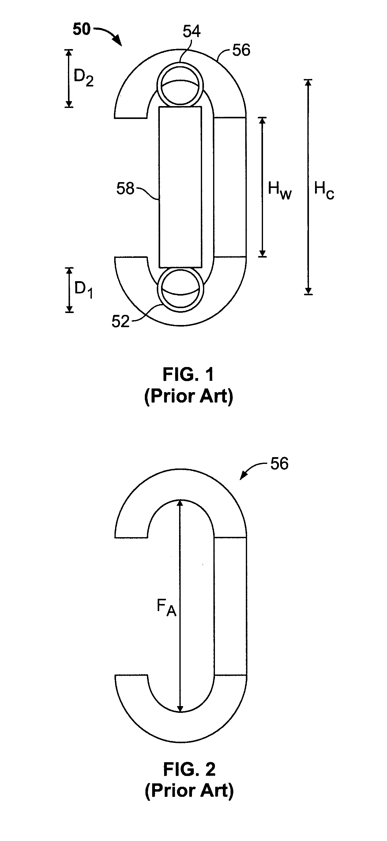
[0022]FIGS. 1 and 2 illustrate a known wedge connector assembly 50 for power utility applications wherein mechanical and electrical connections between a tap or distribution conductor 52 and a main power conductor 54 are to be established. The connector assembly 50 includes a C-shaped spring member 56 and a wedge member 58. The spring member 56 hooks over the main power conductor 54 and the tap conductor 52, and the wedge member 58 is driven through the spring member 56 to clamp the conductors 52, 54 between the ends of the wedge member 58 and the ends of the spring member 56.

[0023] The wedge member 58 may be installed with special tooling having for example, gunpowder packed cartridges, and as the wedge member 58 is forced into the spring member 56, the ends of the spring member 56 are deflected outwardly and away from one another via the applied force FA shown in FIG. 2. Typically, the wedge member 58 is fully driven to a final position wherein the rear end of the wedge member 58...


PUM


Abstract

An electrical connector assembly includes a bail, a first conductive member having a first hook portion extending from a first wedge portion, wherein the first hook portion adapted to engage a main conductor, and a second conductive member having a second hook portion extending from a second wedge portion. The second hook portion is adapted to engage the bail. The first wedge portion and the second wedge portion are adapted to nest with one another and be secured to one another to capture and electrically connect the main conductor and the bail.

Description

CROSS REFERENCE TO RELATED APPLICATIONS [0001] This application is a continuation-in-part of U.S. application Ser. No. 11 / 437,480, filed May 18, 2006, and entitled “Combination Wedge Tap Connector”, which is hereby incorporated by reference in its entirety.BACKGROUND OF THE INVENTION [0002] The subject matter herein relates generally to electrical connectors, and more particularly, to power utility connectors for providing a power take-off location from a main electrical transmission conductor. [0003] Electrical utility firms constructing, operating and maintaining overhead and / or underground power distribution networks and systems utilize connectors to tap main power transmission conductors and feed electrical power to distribution line conductors, sometimes referred to as tap conductors. The main power line conductors and the tap conductors are typically high voltage cables that are relatively large in diameter, and the main power line conductor may be differently sized from the t...

Claims


Application Information

Patent Timeline
IPC IPC(8): H01R4/44
CPCH01R4/5091H01R4/38
Inventor COPPER, CHARLES DUDLEYLADIN, DMITRY
Owner TYCO ELECTRONICS CANADA
Why Eureka
Try Eureka