Rotational angle detector

a detector and rotational angle technology, applied in the direction of instruments, vessel construction, steering initiation, etc., can solve the problems of deteriorating detection accuracy of steering angle, clattering of worm gear, and clattering becoming larger, so as to achieve less clattering and high detection precision

Inactive Publication Date: 2008-02-28
NILES PARTS CO LTD
View PDF4 Cites 19 Cited by
  • Summary
  • Abstract
  • Description
  • Claims
  • Application Information

AI Technical Summary

Benefits of technology

[0017]An object of the present invention is to provide a rotational angle

Problems solved by technology

However, since these steering wheels rotate, for example, respectively 720° to the left and right directions, for example, “how many rotation numbers are to the right” cannot be detected only by performing detection of the rotational state of one rotational angle detecting gear which rotates in association with the steering shaft.
Clatt

Method used


Image

  • Rotational angle detector
  • Rotational angle detector
  • Rotational angle detector

Examples


Embodiment Construction

[0033]A selected preferred embodiment of the present invention will now be explained with reference to the drawings. It will be apparent to those skilled in the art from this disclosure that the following description of the embodiment of the present invention is provided for illustration only, and not for the purpose of limiting the invention as defined by the appended claims and their equivalents.

[0034]Now, description is made of an embodiment of the present invention.

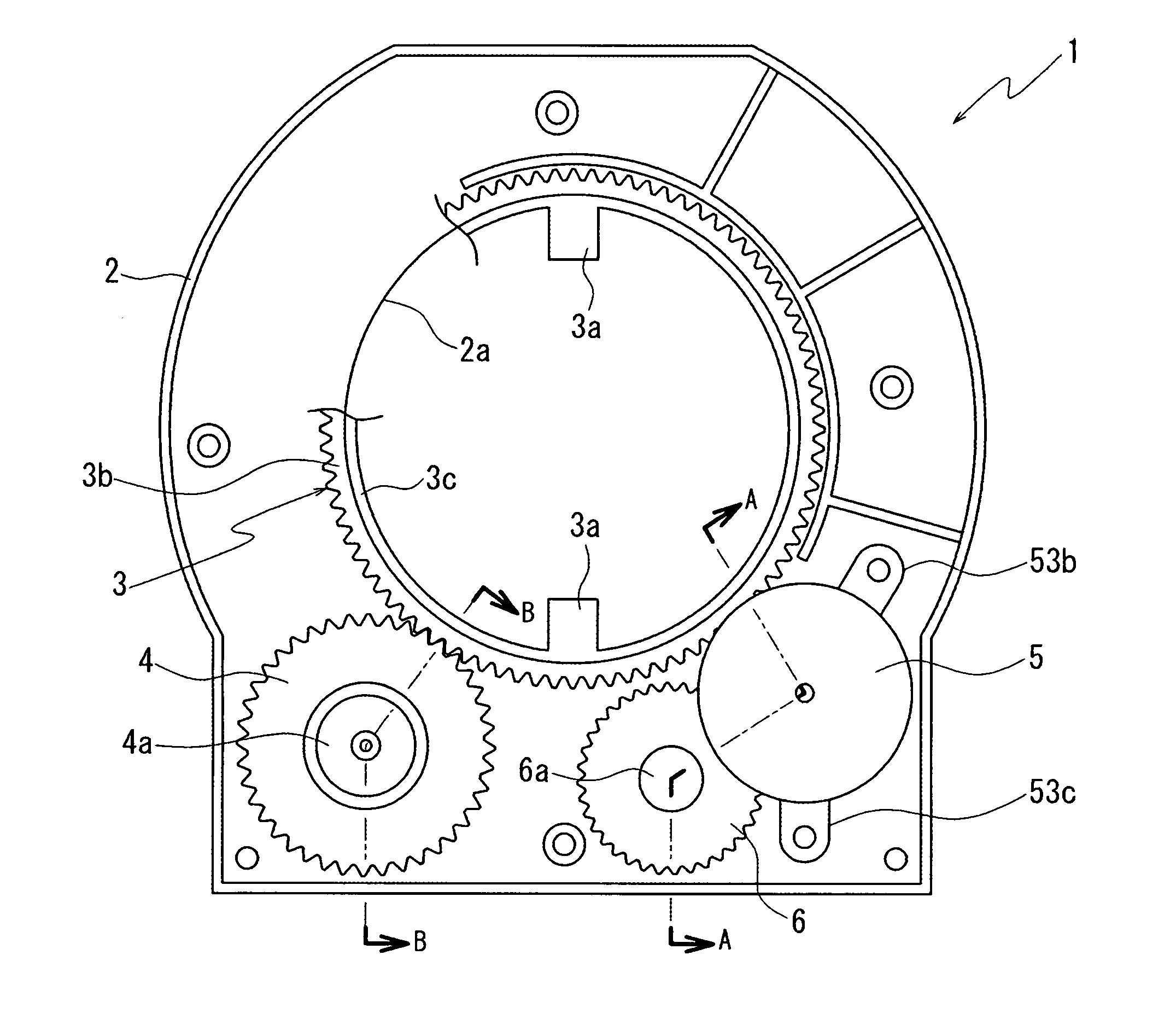
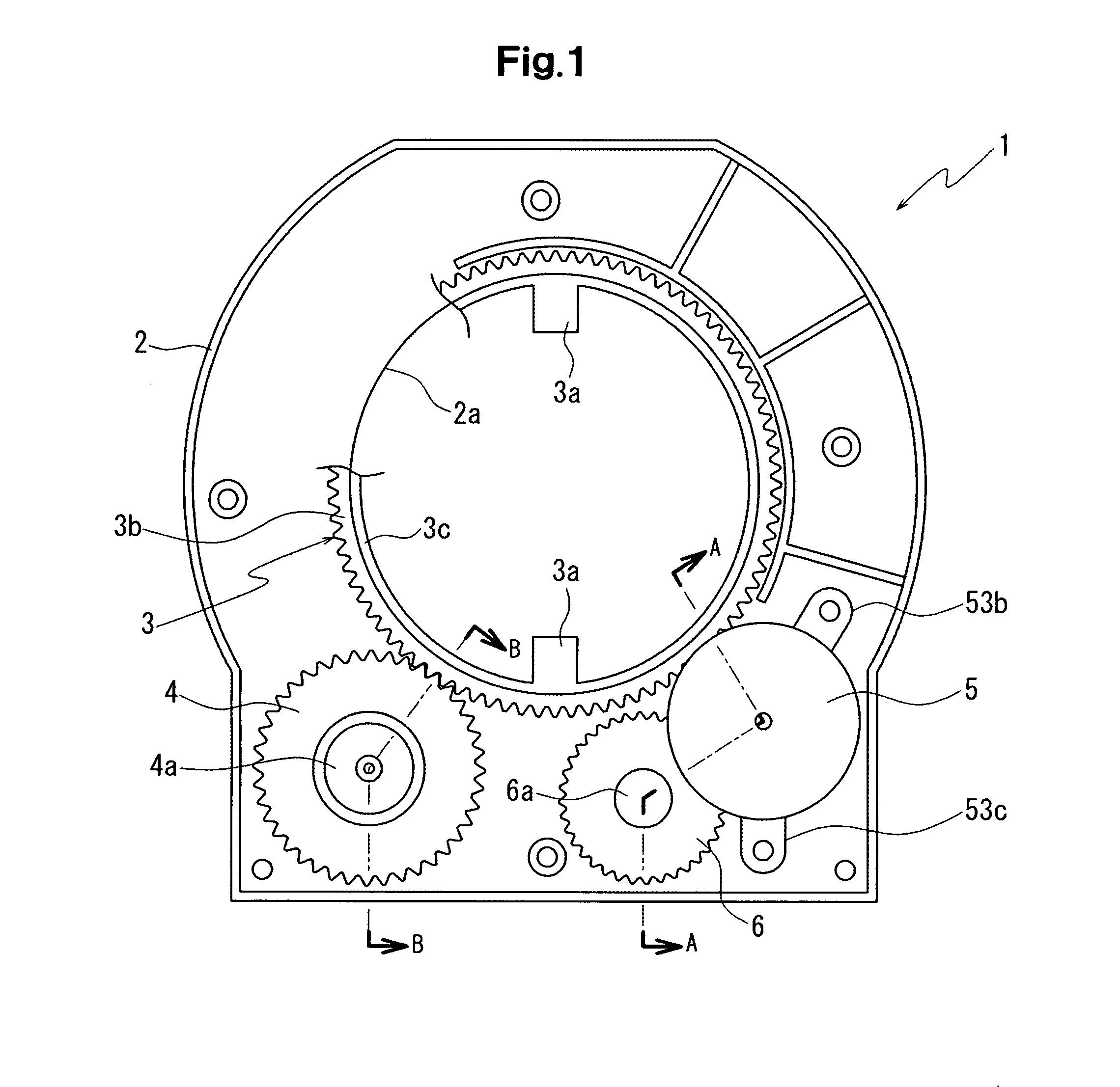
[0035]FIG. 1 shows a state in which respective gears are assembled in a case 2, FIG. 2(a) shows a state in which a substrate 7 is assembled, and FIG. 2(b) shows a state in which a terminal block 8 is assembled. Further, FIG. 3 shows an upper plane of a rotational angle detector.

[0036]It should be noted that, in FIG. 1, a part of a rotor gear 3 is broken in order to show an opening section 2a of the case 2.

[0037]Further, FIG. 4 shows an enlargement of A-A sectional plane in FIG. 1, and FIG. 5 shows an enlargement of B-...


PUM


Abstract

Since rotation of a rotor gear which rotates integrally with a steering shaft is made to reduce by a speed reduction system constituted by a planetary gear system, and rotation after the speed reduction is made to be transmitted to a speed reduction side detecting gear, transmission efficiency of the rotation is improved, and since shafts of respective gears constituting the speed reduction system are directed to the same direction, the rotation of the steering shaft can be transmitted to the speed reduction side detecting gear with reduced clattering. Accordingly, since the clattering at the speed reduction system is reduced, the rotational angle of the steering shaft can be detected more accurately.

Description

CROSS-REFERENCE TO RELATED APPLICATION[0001]This application is based on Japanese Patent Application No. 2006-228581 filed on Aug. 25, 2006, the disclosure of which is incorporated herein by reference.BACKGROUND OF THE INVENTION[0002]1. Field of the Invention[0003]The present invention relates to a rotational angle detector for detecting a rotational state of a steering shaft mounted on a vehicle.[0004]2. The Related Art of the Invention[0005]Conventionally, there is a rotational angle detector for detecting an absolute steering angle of a steering shaft connected to a steering wheel of a vehicle, and for outputting a detected result to another control apparatus or the like.[0006]In such a detector, a gear is fitted into the steering shaft for detecting a rotational state of a rotational angle detecting gear connected to the gear. Further, the rotational angle detecting gear is made to rotate in a larger rotation speed than the rotation speed of the steering gear, such that the rota...

Claims


Application Information

Patent Timeline
IPC IPC(8): G01P3/00
CPCB62D15/0215B62D15/0245G01B21/22G01D11/10G01D5/24452G01D5/24461G01D5/2449G01D5/04G01D18/001G01D2205/26G01B7/30
Inventor EBASHI, AKIOSATO, YASUHIRO
Owner NILES PARTS CO LTD
Why Eureka
Try Eureka