Magnetic detector maintaining high detection precision without affected by the temperature characteristics of the sensing element

a technology of magnetic detector and temperature characteristic, applied in the field of magnetic detector, to achieve the effect of correct detection precision

Active Publication Date: 2008-12-23
MITSUBISHI ELECTRIC CORP
View PDF5 Cites 2 Cited by
  • Summary
  • Abstract
  • Description
  • Claims
  • Application Information

AI Technical Summary

Benefits of technology

[0008]It is therefore an object of the present invention to provide a magnetic detector which is so constituted as to impart a phase difference of ¼ period to between the output of the third bridge circuit and the differential output of the first and second bridge circuits, and is capable of maintaining a correct detection precision even when a temperature offset has occurred.
[0015]The present invention provides a magnetic detector which stably maintains a high detection precision without affected by the temperature characteristics of the magnetic / electric conversion element or by dispersion in the fabrication.

Problems solved by technology

The problem of offset is caused not only by a change in the temperature characteristics of the magnetic / electric conversion elements but also by dispersion in the fabrication of the magnetic / electric conversion elements.

Method used


Image

  • Magnetic detector maintaining high detection precision without affected by the temperature characteristics of the sensing element
  • Magnetic detector maintaining high detection precision without affected by the temperature characteristics of the sensing element
  • Magnetic detector maintaining high detection precision without affected by the temperature characteristics of the sensing element

Examples


embodiment 1

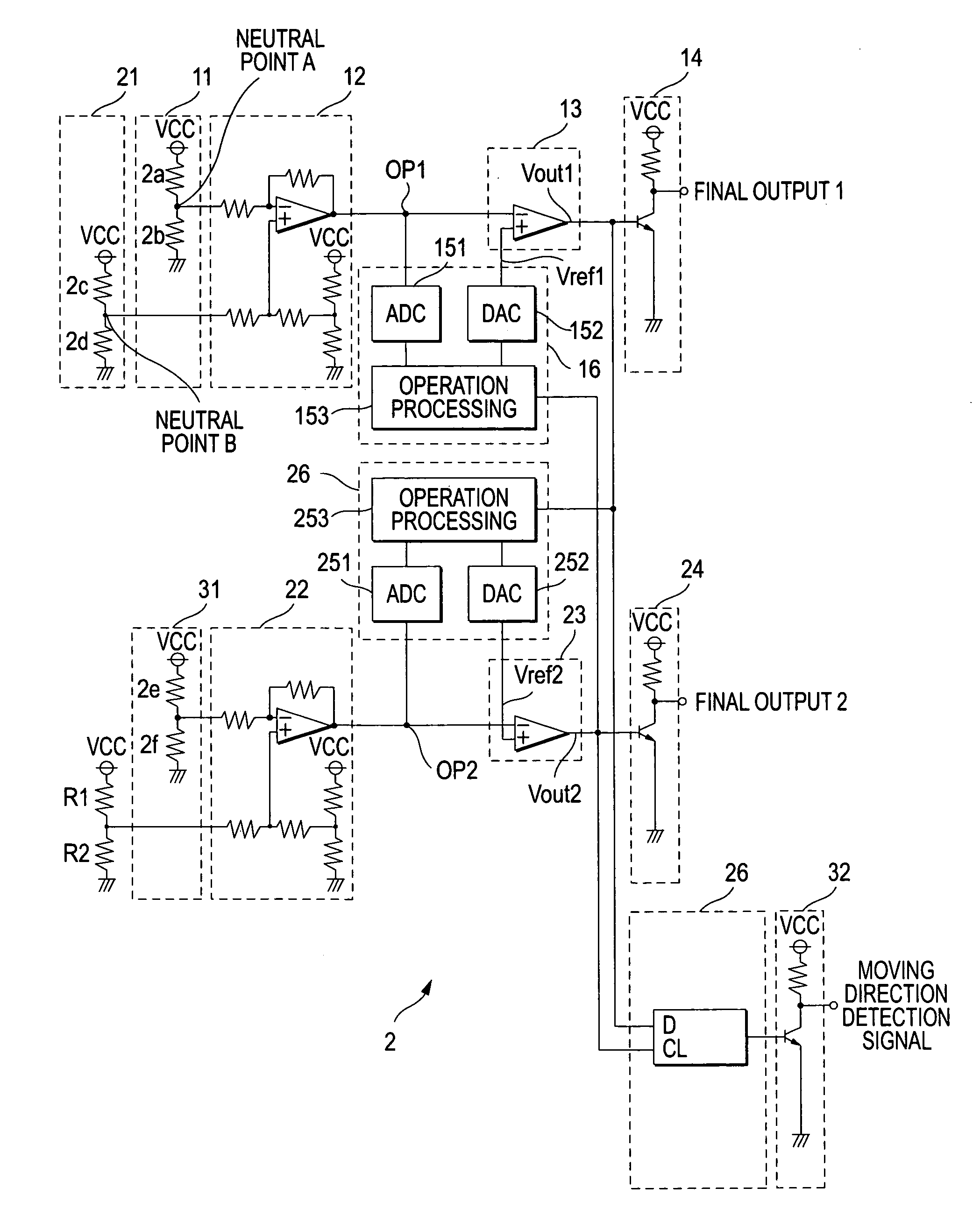
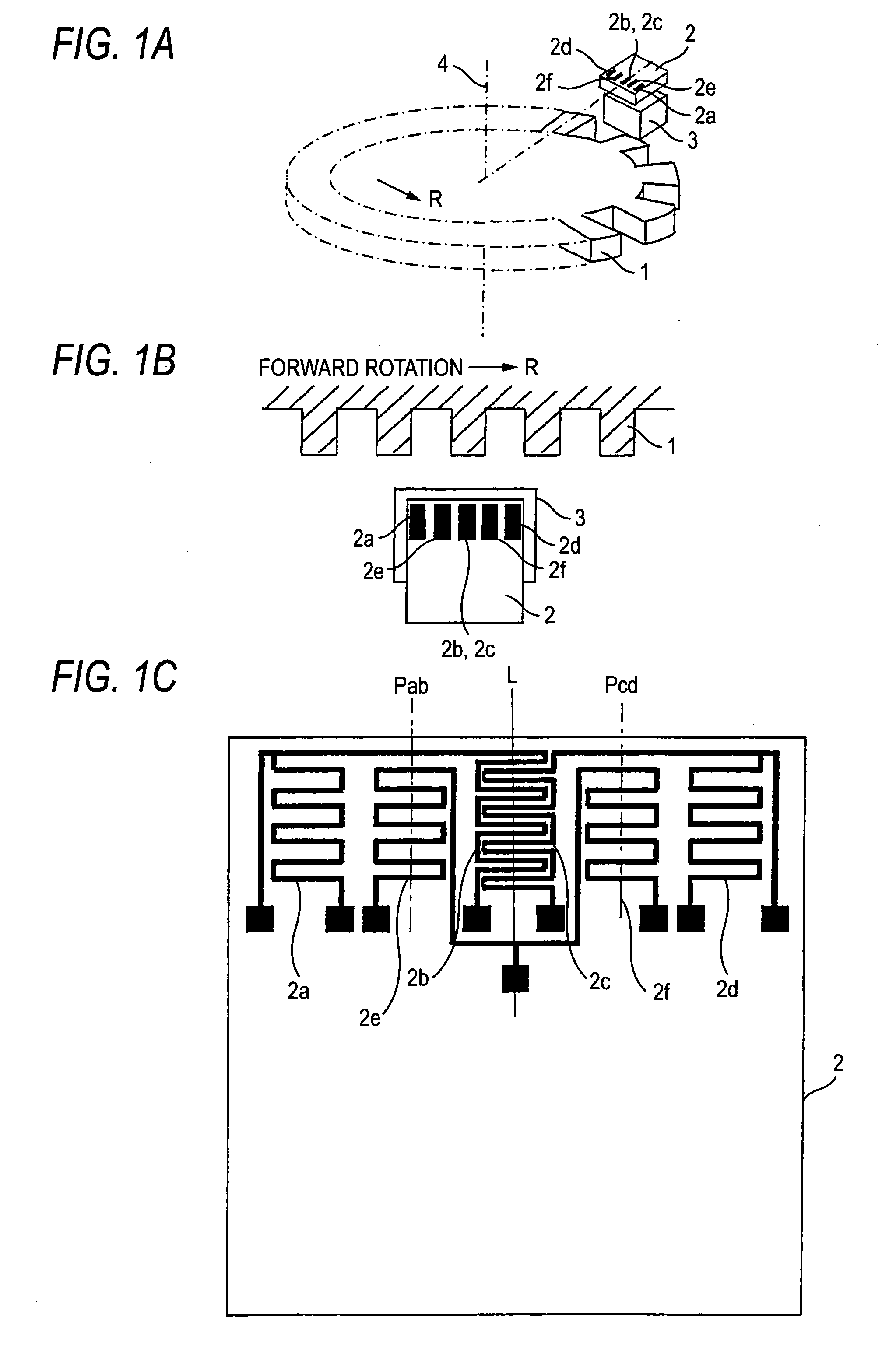
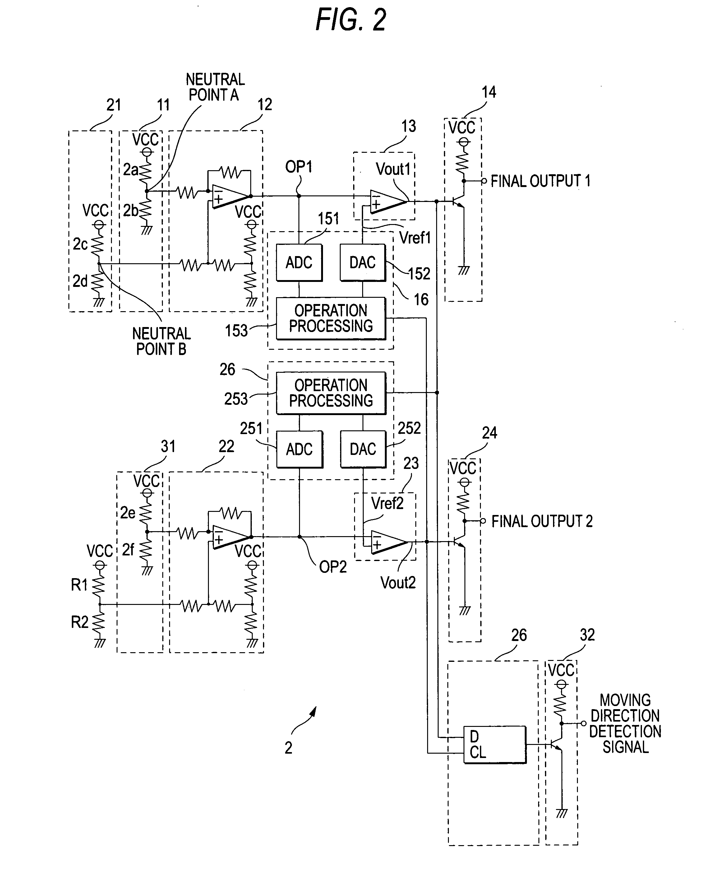
[0022]A first embodiment of the invention will now be described. FIG. 1 is a view illustrating the whole constitution of a magnetic detector according to the invention, wherein FIG. 1A is a perspective view illustrating the constitution of a magnetic circuit, FIG. 1B is a top view illustrating a portion thereof on an enlarged scale, and FIG. 1C is a view of a pattern of reluctance segments on an enlarged scale. FIG. 2 is a diagram illustrating the constitution of a signal-processing circuit in detail. In the drawings, reference numeral 1 denotes a magnetic moving body having a shape that varies the magnetic field, and 2 denotes a signal-processing circuit portion which is constituted by an IC chip.

[0023]Reference numeral 3 denotes a magnet which is arranged facing the magnetic moving body 1 and is magnetized in the direction of rotary shaft of the magnetic moving body, and 4 denotes a rotary shaft. As the rotary shaft 4 rotates, the magnetic moving body 1 rotates in synchronism ther...


PUM


Abstract

A magnetic detector, wherein the magnetic / electric conversion element is constituted by at least six segments symmetrically arranged in a direction in which the magnetic moving body rotates maintaining a predetermined pitch with respect to the center line of the magnet, first and second bridge circuits are constituted so as to produce outputs accompanying the rotation of the magnetic moving body, and a third bridge circuit is constituted so as to produce an output accompanying the rotation of the magnetic moving body, and wherein a comparison level of a comparator circuit that shapes the waveform of a differential output signal of the first and second bridge circuits is adjusted relying upon an output signal of the third bridge circuit.

Description

BACKGROUND OF THE INVENTION[0001]1. Field of the Invention[0002]This invention relates to a magnetic detector using reluctance segments and, more particularly, to a magnetic detector capable of detecting a change in the magnetic field caused by the motion of a magnetic moving body coupled to an object that is to be detected.[0003]2. Description of the Related Art[0004]In recent years, a car-mounted rotation sensor and the like are utilizing a magnetic detector which detects a change in the magnetic field acting on the reluctance elements by constituting a bridge circuit by forming electrodes at the ends of the reluctance segments, connecting a constant-voltage and constant-current source between the two opposing electrodes of the bridge circuit, and converting a change in the resistance of the reluctance segments into a change in the voltage, and various proposals have been made so far.[0005]A conventional magnetic detector has been disclosed in, for example, JP-A-2005-156368 accord...

Claims


Application Information

Patent Timeline
Patent Type & Authority Patents(United States)
IPC IPC(8): G01B7/30
CPCG01D5/24438G01R33/09
Inventor YOKOTANI, MASAHIROHIRAOKA, NAOKI
Owner MITSUBISHI ELECTRIC CORP
Why Eureka
Try Eureka