Liquid level sensor and method of manufacturing the same

a liquid level sensor and sensor chamber technology, applied in liquid/fluent solid measurement, instruments, machines/engines, etc., can solve the problems of reducing the thickness of the non-contact type liquid level sensor and the cost to manufacture, deteriorating performance of electronic parts, and damage to the sealing of the sensor chamber by the related sealing method, etc., to achieve high detection accuracy, high accuracy, and excellent durability

Active Publication Date: 2007-06-05
YAZAKI CORP
View PDF9 Cites 2 Cited by
  • Summary
  • Abstract
  • Description
  • Claims
  • Application Information

AI Technical Summary

Benefits of technology

[0021]It is therefore an object of the present invention to provide a non-contact type liquid level sensor which liquid tightly seals electronic parts having electric circuitries for a long term and stably, and restricts the displacement of the constituent parts in accordance with the ambient environmental temperature variation and the vibration to thereby keep a detection precision in high level and stably.
[0031]In the configurations, the magnetoelectric transducing element, the electronic parts, and the pair of stators are fixed to predetermined positions of the set of terminals to thereby form the terminal assembly, and the terminal assembly is insert molded into the housing, whereby the terminal assembly is embedded in the housing. The result is to reliably prevent seal leaking caused by poor welding of the cover, which is inevitable in the related cover, to protect the electric circuit for a long time, and hence, to maintain a high detection precision of the non-contact type liquid level sensor for a long term.
[0032]Also, the magnetoelectric transducing element, the electronic parts, the pair of stators, the terminals and others are fixedly embedded in the resin of the housing. Therefore, the vibration proof performance of the non-contact type liquid level sensor is remarkably improved. There is eliminated troublesome works, such as welding work of the cover and work of coating the soldered parts with a potting agent. The cost of manufacturing the non-contact type liquid level sensor is reduced. Further, there is eliminated the necessity of large facility investment for the laser welding machine and the vibration welding machine.
[0036]In the configuration, after the sealing parts which are located near connection parts of the terminals and embedded in the housing are coated with a sealing agent, the terminal assembly is insert molded into the housing. A reliable sealing between the housing and the terminals is ensured. Therefore, the sealing performance is stably kept for a long time. Accordingly, there is eliminated the adverse influence of fuel or the like onto the electronic parts, and hence, a high detection precision of the liquid level sensor is maintained for a long time.
[0046]In the above methods, the magnetoelectric transducing element, the electronic parts, and the pair of stators are fixedly embedded in the housing. The magnetoelectric transducing element, the electronic parts and the pair of stators are never displaced by vibrations and the like caused when the vehicle runs. Accordingly, those parts and components are assembled at high accurate positions and easily. Accordingly, a liquid level sensor which is excellent in durability, and high in detection accuracy and reliability can be manufactured at low cost.

Problems solved by technology

Those technical features bring about the reduction of the thickness of the non-contact type liquid level sensor and the cost to manufacture.
Neither of those patent documents, however, discloses a technique to avoid such an unwanted situation that the electronic parts come in contact with fuel, such as gasoline, and the performances of the electronic parts are deteriorated, by liquid-tightly sealing electronic parts, such as the hall element.
The sealing of the sensor chamber sealed by the related sealing method is damaged by dimensional variation and deformation of the housing 2, the cover 35 or partial poor welding.
A laser welding machine used for welding the cover 35 to the housing 2 is expensive, and large facility investment is needed.
In this respect, use of such a sealing technique has economical problems to be solved.
Further, the work to apply the potting agent to the soldering portion, and the work to apply the seal coating material to the terminal 13 before the insert molding process are inevitably manual, and troublesome.
In this respective, the productivity in manufacturing the sensors is inferior.

Method used


Image

  • Liquid level sensor and method of manufacturing the same
  • Liquid level sensor and method of manufacturing the same
  • Liquid level sensor and method of manufacturing the same

Examples


first embodiment

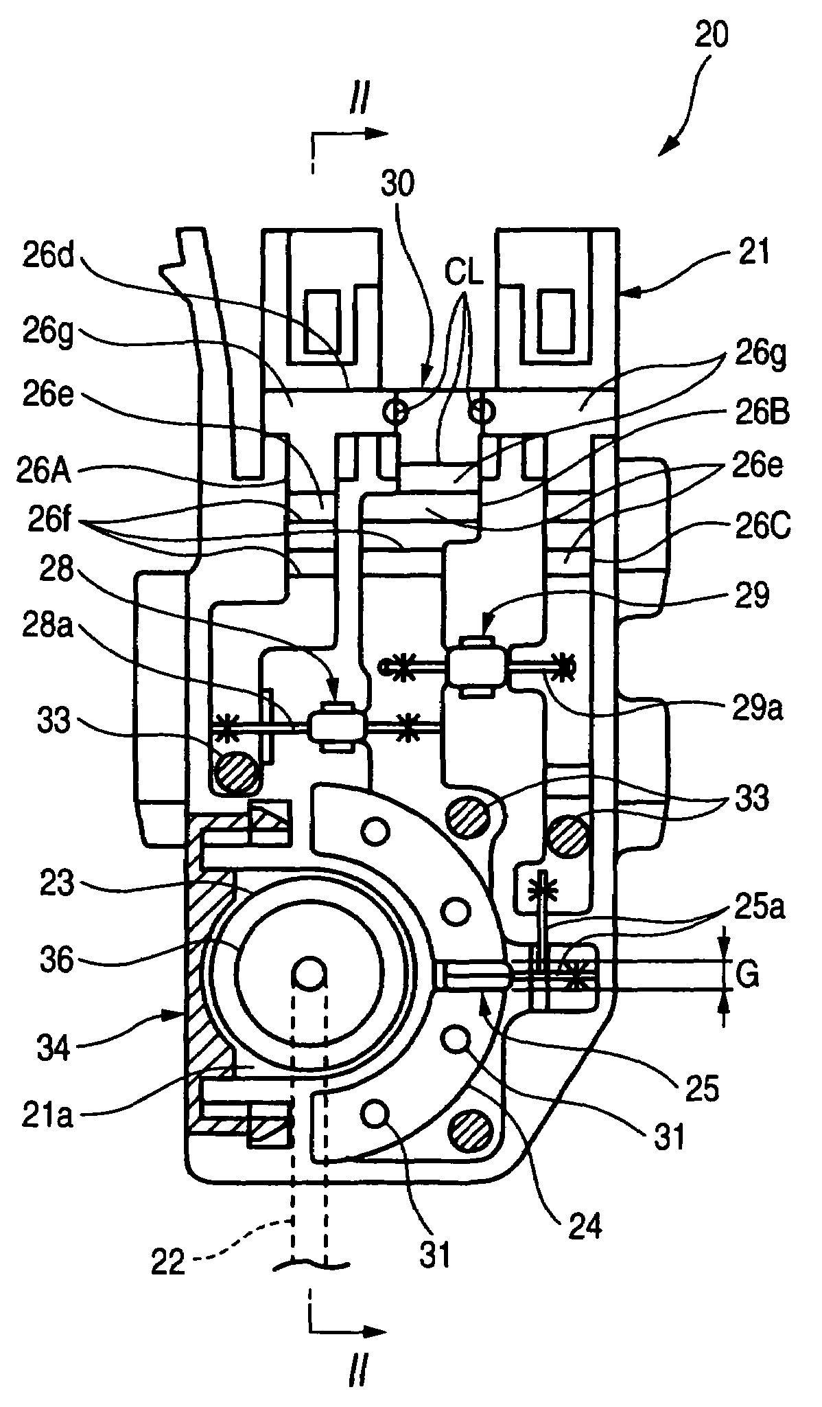
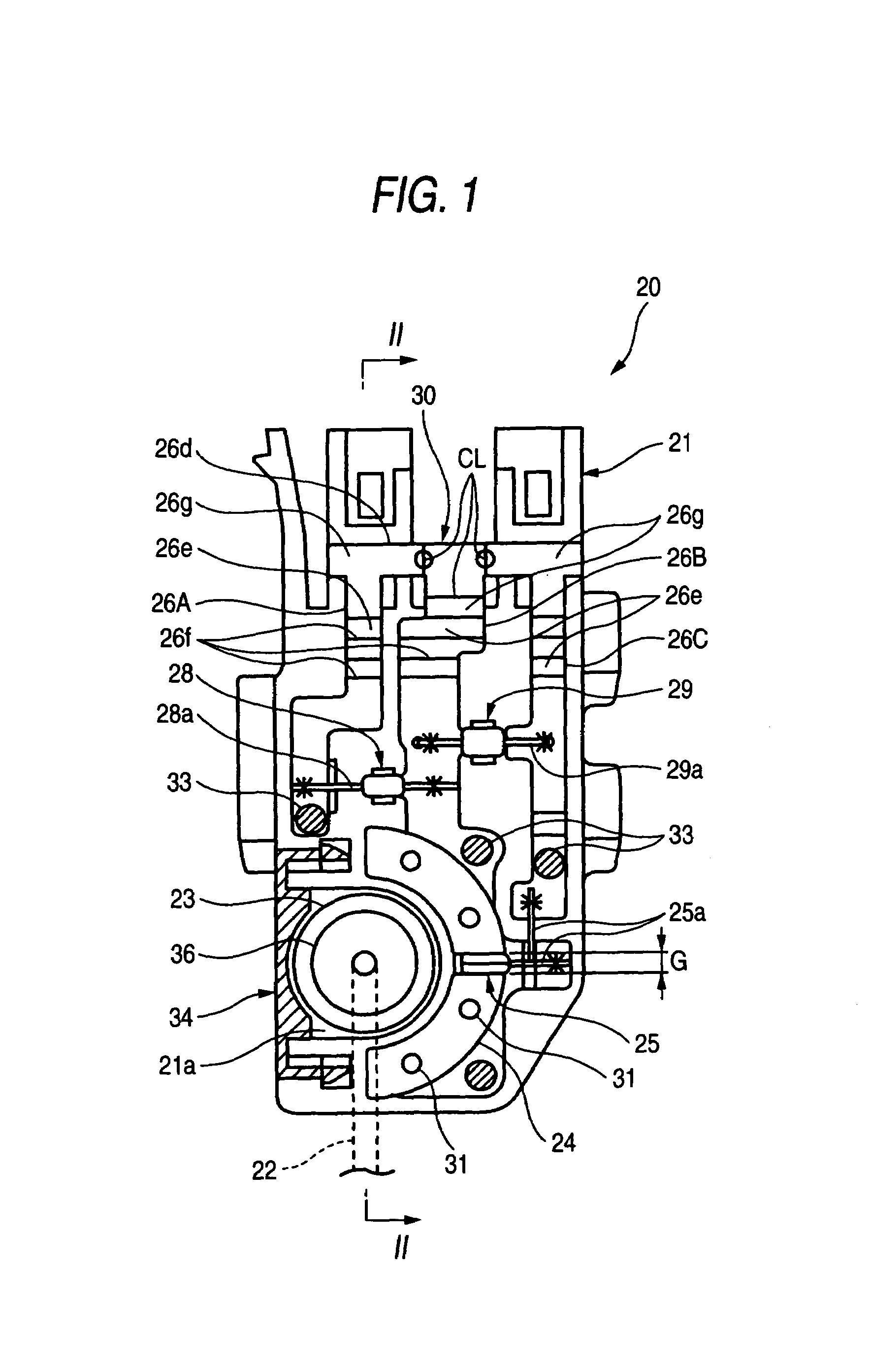
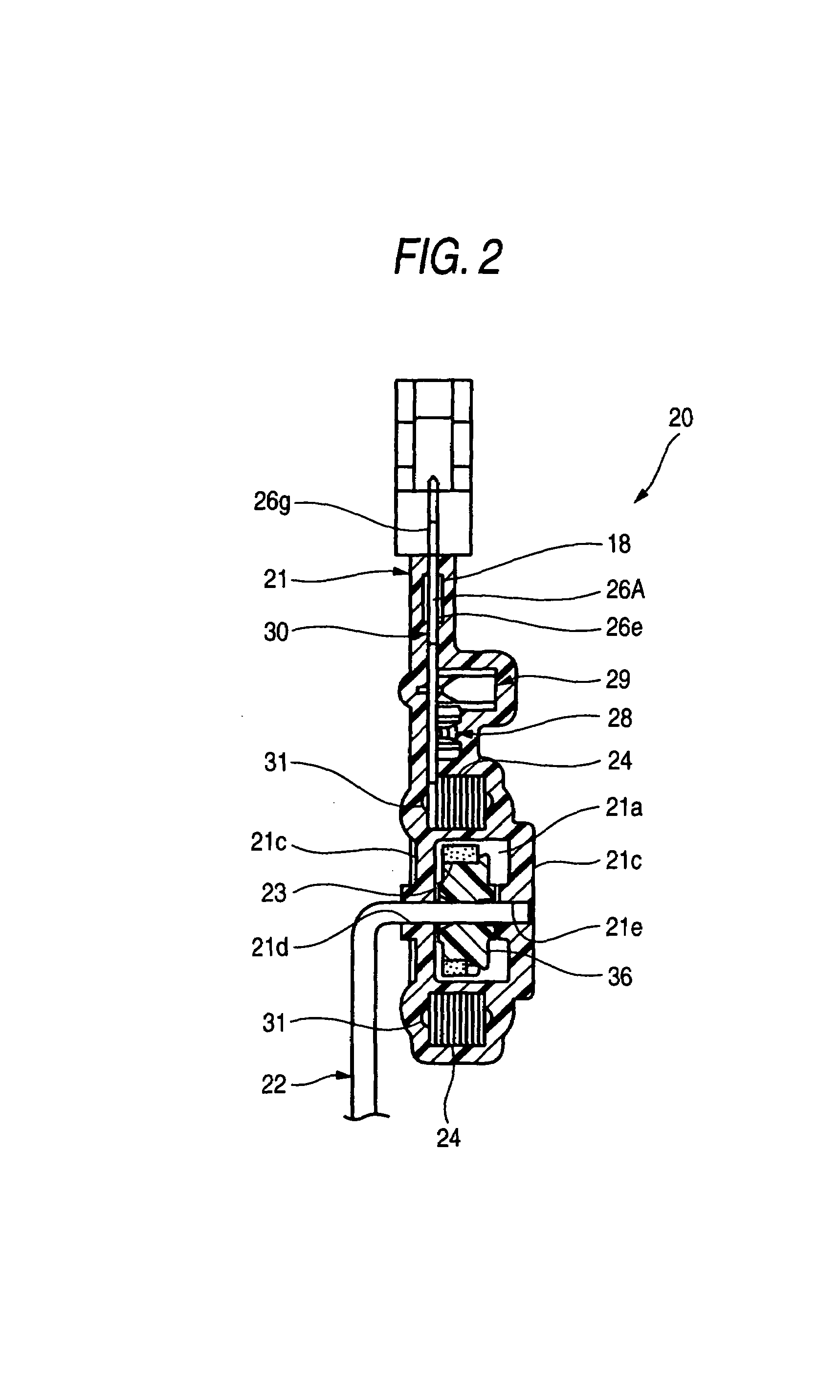
[0063]A non-contact type liquid level sensor according to the present invention will be described with reference to FIGS. 1 to 7.

[0064]As shown in FIGS. 1 and 2, in a non-contact type liquid level sensor 20 according to the first embodiment of the invention, a terminal assembly 30 is insert molded into the housing 21. Most part of the terminal assembly 30 except outer connection parts 26g is embedded in the synthetic resin of the housing 21.

[0065]As shown in FIG. 3, the terminal assembly 30 includes an assembly of terminals 26A, 26B and 26C, a magnetoelectric transducing element 25, a resistor 28, a capacitor 29 and a couple of stators 24 which are assembled. The terminals 26A, 26B and 26C form a part of an electric circuit. Those terminals are provided for transferring an electric signal, which is detected by and output from the magnetoelectric transducing element 25, to exterior. Three different terminals 26A, 26B which are formed by pressing a conductive metal plate and have diff...

second embodiment

[0088]A float arm 40 of the second embodiment is different from the related float arm in that a collar 40a is formed at a position of the float arm near its bent part, as shown in FIG. 9. A press-fitting device 41 is used for press fitting the float arm 40 into the rotary shaft 36.

[0089]As shown in FIG. 10, the press-fitting device 41 includes a fixing jig 42 for fixedly setting the housing 21 at a predetermined location, and a press-fitting bar 43. The fixing jig 42 includes a receiving jig 44 which is slidable in a horizontal direction. The receiving jig supports a lower end surface of the rotary shaft 36 located within the magnet containing portion 21a (see FIG. 9). When an operation lever 45 is operated, the press-fitting bar 43 is vertically (in FIG. 10) moved by an action of a rack / pinion mechanism (not shown). A groove 43a is formed in a tip end part of the press-fitting bar 43. The groove receives the bent part of the float arm 40.

[0090]To press fit the float arm 40 into the...

third embodiment

[0092]Next, a liquid level sensor will be described with reference to FIGS. 11 to 13.

[0093]The third embodiment is featured in that a rotary shaft 50 and a magnet containing portion cover 51 are different in shape from those in the first embodiment shown in FIGS. 1 through 7. As shown in FIG. 11, the rotary shaft 50 of the third embodiment consists of a cylindrical member with a sintered magnet 23 fit onto the center of the outer peripheral surface thereof. A through hole 50b passes through an axial center of the rotary shaft, and a shaft part 50a protrudes from one side of the rotary shaft. The shaft part 50a is fit into one through hole 21e of the housing 21 in a rotatable state. The float arm 22 which has passed through the through hole 21d of the housing 21 is press fit into the through hole 50b of the rotary shaft 50. With this structure, the rotary shaft 50 is rotatably supported in the magnet containing portion 21a by the float arm 22 having passed through the shaft part 50a...


PUM


Abstract

A liquid level sensor includes a housing, a rotary shaft which is rotatably provided in the housing, a magnet which is fixed to the rotary shaft, and rotating together with the rotary shaft, a pair of stators which are disposed so as to face an outer peripheral surface of the magnet, and an electronic circuit which includes at least a set of terminals and a magnetoelectric transducing element for detecting a change of magnetic flux in the stators caused by rotation of the magnet and for outputting an electric signal. The magnetoelectric transducing element and the stators are electrically connected and fixed to the set of terminals so that a terminal assembly is formed. The housing is formed by insert molding the terminal assembly with resin so that the terminal assembly is embedded in the housing.

Description

BACKGROUND OF THE INVENTION[0001]The present invention relates to a liquid level sensor and a method of manufacturing the same. More particularly, the invention relates to a non-contact type liquid level sensor which is improved in the vibration proof performance, and reduced in a sensor output variation caused by a change of an ambient environment temperature, whereby the liquid level sensor accurately detects a liquid level, and which is well adaptable for a vehicle fuel tank or the like, and a method of manufacturing the non-contact type liquid level sensor.[0002]Recently, a liquid level sensor of the non-contact type, for example, is mounted on a fuel tank of a vehicle, such as an automobile, and detects an amount of fuel liquid contained in the fuel tank. In a related liquid level sensor, an annular magnet which rotates with movement of a float is disposed within a frame. A hall element as a magnetoelectric transducing element is disposed at the center of the magnet, while bein...

Claims


Application Information

Patent Timeline
Patent Type & Authority Patents(United States)
IPC IPC(8): G01F23/00G01F23/38
CPCG01F23/38
Inventor TANAKA, KENICHIFUKUHARA, TOSHIAKITAKAHASHI, YUKIO
Owner YAZAKI CORP
Why Eureka
Try Eureka