Wiper

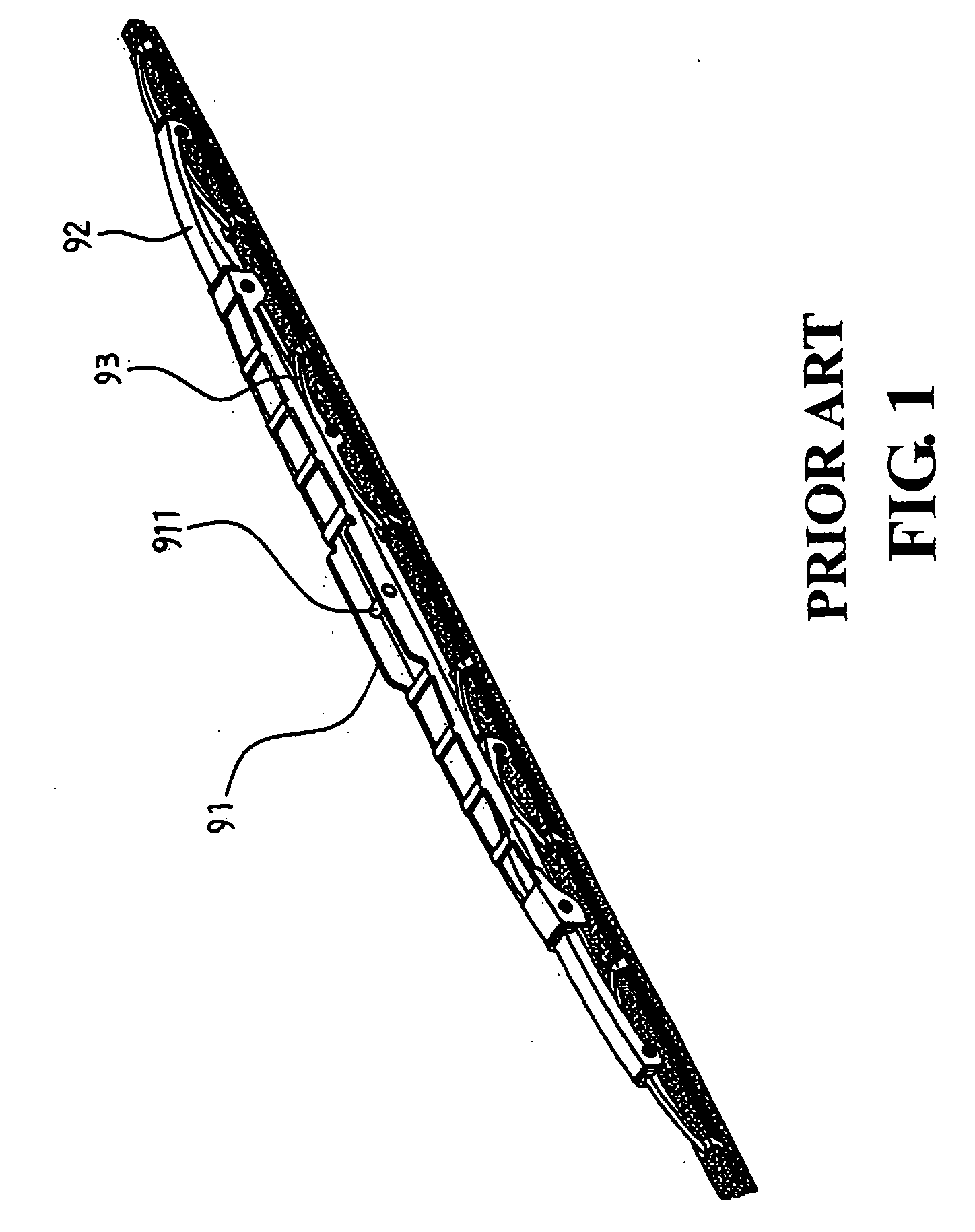
a technology of riveting and wiper, which is applied in the field of riveting, can solve the problems of laborious and cost-ineffective, complicated manufacturing process, and numerous parts which are combined by riveting method

Active Publication Date: 2008-03-06
FU GANG CO LTD
View PDF6 Cites 65 Cited by
  • Summary
  • Abstract
  • Description
  • Claims
  • Application Information

AI Technical Summary

Benefits of technology

[0006]Yet another object of the present invention is to provide a wiper, wherein the horizontal sectional

Problems solved by technology

The drawback of the conventional wiper is the numerous parts which are combined by riveting method.
This i

Method used


Image

  • Wiper
  • Wiper
  • Wiper

Examples


Embodiment Construction

[0019]The following descriptions are of exemplary embodiments only, and are not intended to limit the scope, applicability or configuration of the invention in any way. Rather, the following description provides a convenient illustration for implementing exemplary embodiments of the invention. Various changes to the described embodiments may be made in the function and arrangement of the elements described without departing from the scope of the invention as set forth in the appended claims.

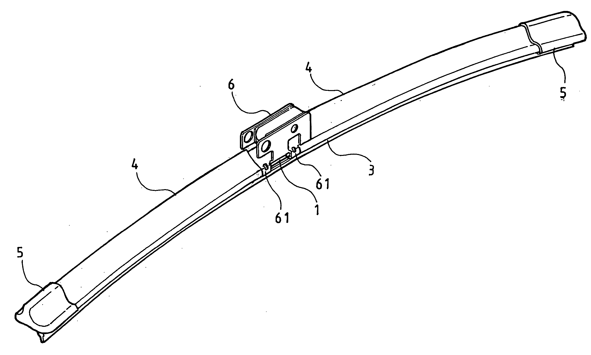
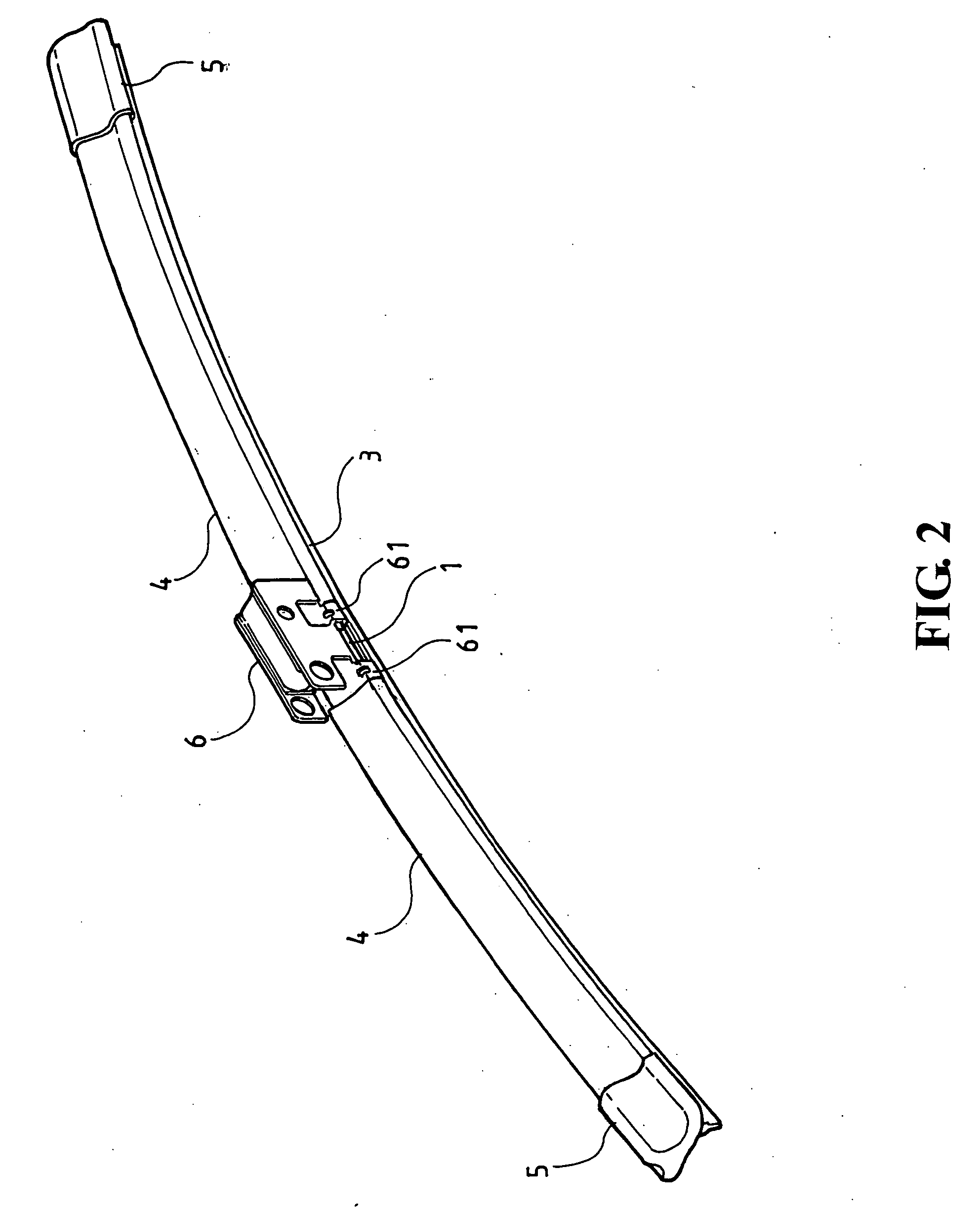
[0020]Referring to FIGS. 2, 3 and 4, there is shown a wiper comprising an elastic plate 1, two securing seat 2, a rubber stripe 3, two rubber covers 4, two protective covers 5 and a fastening rod seat 6. The elastic plate 1 is elongated and the lateral side edge near to the ends of the elastic plate 1 is provided with symmetrical notches 11. The upper section of the securing seat 2 is provided with a U-shaped slot 21, and the lower section of the slot 21 is provided with a grip section 22. The sl...


PUM


Abstract

A wiper is disclosed. The wiper comprises an elastic plate being elongated and having two ends with side edge provided with symmetrical notches; two securing seats provided with a substantially U-shaped slot and a grip section provided below the slot having a plurality of horizontal sectional holes; two rubber covers which are pointed and the bottom edge of the side edge of the cover being an inward hook section; and a bottom edge mounted with a buttoning rod seat with an engaging hook and a rubber stripe, whereby the elastic plate is mounted at the slot and is then engaged at the rubber cover, the grip is mounted with the rubber stripe and the center of the elastic plate and the two ends thereof are respectively securing to the buttoning rod seat and a protective cover, forming into the wiper.

Description

BACKGROUND OF THE INVENTION[0001](a) Technical Field of the Invention[0002]The present invention relates to wiper, and in particular, to wiper which is easily mounted and provides excellent wiping on the surface of windscreen of a vehicle.[0003](b) Description of the Prior Art[0004]FIG. 1 shows a conventional wiper comprising a large frame 91, a middle frame 92 and a small frame 93. A fastening rod 911 is provided on the large frame 91 for mounting onto the wiper arm of a vehicle. The drawback of the conventional wiper is the numerous parts which are combined by riveting method. This is laborious and cost-ineffective and the entire manufacturing process is complicated and the yield is low. Accordingly, it is an object of the present invention to provide a wiper which mitigates the above-drawbacks.SUMMARY OF THE INVENTION[0005]The primary purpose of the present invention is to provide a wiper comprising an elastic plate being elongated and having two ends with side edge provided with...

Claims


Application Information

Patent Timeline
IPC IPC(8): B60S1/38
CPCB60S1/38B60S1/381B60S1/3856B60S2001/3822B60S1/3889B60S2001/3817B60S1/3881
Inventor CHIANG, MIN-HENG
Owner FU GANG CO LTD
Why Eureka
Try Eureka